Multiple 5v relays inline

Guitarnerd

Jan 25, 2025
9
Joined
Jan 25, 2025
Messages
9
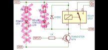
Hi. I have a project where I'm using 6 5v pcb coil relays so that one power source will switch all 6 at one time. I usually use the pre-made boards but have a space constraint so I thought I'd be able to just use the switch coils by themselves. I tried one and it worked fine so I wired up all 6 and things got a little nuts. The relays would not switch and my volt meter was reading around 0.6v where the supply voltage was a little over 5v. I'm clearly doing something wrong but not sure what that is. Any guidance would be greatly appreciated.
 

Bluejets

Oct 5, 2014
7,374
Joined
Oct 5, 2014
Messages
7,374
Place coils in parallel, use a power supply sufficiently sized for all 6 coils (plus about 50% margin to allow for inrush current).
No idea where you are measuring power or how your connections are made so supply a photo and a pencil sketch of everything.
 

Martaine2005

May 12, 2015
5,276
Joined
May 12, 2015
Messages
5,276
What PIN numbers are you connecting to?.
Perhaps you have a current limit set too low for 6 coils on your power supply?
 

danadak

Feb 19, 2021
1,062
Joined
Feb 19, 2021
Messages
1,062
This is correct way to wire these for operation off 5V.

1737802302739.png

Your nominal current is ~90 mA / relay, so 450 mA required by supply.

What exactly is the supply, eg. schematic ?

Note there should not be an inrush current per se as they are inductive in
nature, question is are they low Q so current transient pretty damped....
But there is a minimum V, I needed to get them to turn on. And then holding
V, I is lower.

Regards, Dana.
 
Last edited:

Guitarnerd

Jan 25, 2025
9
Joined
Jan 25, 2025
Messages
9
This is correct way to wire these for operation off 5V.

View attachment 65578

Your nominal current is ~90 mA / relay, so 450 mA required by supply.

What exactly is the supply, eg. schematic ?

Note there should not be an inrush current per se as they are inductive in
nature, question is are they low Q so current transient pretty damped....
But there is a minimum V, I needed to get them to turn on. And then holding
V, I is lower.

Regards, Dana.
That all makes sense to me. The power supply is a OneSpot, so, 9vdc 1700mA. I have it passing through a voltage regulator that drops it to about 5.5vdc. I had the negative tied to the regulator and the positive coming from pin 9 on an an Arduino Leonardo. Maybe, as noted by Martaine2005 the pin can't push enough voltage to it?
 

bertus

Moderator
Nov 8, 2019
3,835
Joined
Nov 8, 2019
Messages
3,835
Hello,

The relays can not be driven by an arduino pin.
You will need a buffer between the arduino pin and the relays.

Bertus
 

Bluejets

Oct 5, 2014
7,374
Joined
Oct 5, 2014
Messages
7,374
Also, some relays will have a freewheeling diode installed and incorrect coil connection will cause the diode to short the supply.
 

danadak

Feb 19, 2021
1,062
Joined
Feb 19, 2021
Messages
1,062
You have to read datasheets and their pin ratings to succeed at designs.

From the data sheet look at pin and max allowed current in the MCU supply
rail ratings :

1737849494127.png
 

Guitarnerd

Jan 25, 2025
9
Joined
Jan 25, 2025
Messages
9
So, I'm thinking about adding a7th relay that triggers from the arduino and that one relay will switch power to all the others. That should work, right? The arduino can switch one relay at 5v 72mA for the one relay, can't it?
 

danadak

Feb 19, 2021
1,062
Joined
Feb 19, 2021
Messages
1,062
See the DC current in the previous post ratings ?

And the logic level specs on a pin -

1737889231184.png

You have to switch the one relay with something like this -

1737889567392.png

Diode 1N4007 or equiv. Transistor 2N3904, 2N2222.......
 

Guitarnerd

Jan 25, 2025
9
Joined
Jan 25, 2025
Messages
9
See the DC current in the previous post ratings ?

And the logic level specs on a pin -

View attachment 65603

You have to switch the one relay with something like this -

View attachment 65605

Diode 1N4007 or equiv. Transistor 2N3904, 2N2222.......
Thank you. I was looking at something that looks very similar. I was planning on this without the indicator leds.
 

Attachments

  • Screenshot_20250126_085253_Gallery.jpg
    Screenshot_20250126_085253_Gallery.jpg
    91.9 KB · Views: 5

danadak

Feb 19, 2021
1,062
Joined
Feb 19, 2021
Messages
1,062
One correction to the earlier post, since you need to drive ~ 450 mA,
a 2N3904, 2N2222 not adequate as the base drive to get the transistor
is ~ 45 mA, too much for the MCU GPIO pin.

Either use a logic level MOSFET (preferred) or a darlington TIP type transistor,
either in a TO220 type package. Say 60 - 100V breakdown to give you plenty
of margin.

Regards, Dana.
 

Guitarnerd

Jan 25, 2025
9
Joined
Jan 25, 2025
Messages
9
One correction to the earlier post, since you need to drive ~ 450 mA,
a 2N3904, 2N2222 not adequate as the base drive to get the transistor
is ~ 45 mA, too much for the MCU GPIO pin.

Either use a logic level MOSFET (preferred) or a darlington TIP type transistor,
either in a TO220 type package. Say 60 - 100V breakdown to give you plenty
of margin.

Regards, Dana.
Like these?
 

Guitarnerd

Jan 25, 2025
9
Joined
Jan 25, 2025
Messages
9
I'm almost done with my project and all the guidance has been a tremendous help. Thank you all!
 
Top