Nick, if you don't mind I am gonna need to pick your brain again. This is really starting to confuse the hell out of me. I did as you asked and read the datasheet this time, but I don't see where it helped me out in this situation. Maybe I am missing something simple and hopefully you can explain it to me. I am glad I caught this before I built the circuit and then not have it work, I can assure you I would have been bouncing my head off the table 20k times trying to figure out why my other orcad sim worked yet the breadboard design did not.
I bought some lm339
N IC chips made by ST. I looked them up on digikey and digi links me to this datasheet found here.
http://search.digikey.com/scripts/DkSearch/dksus.dll?Detail&name=497-1589-5-ND Notice how digikey list the datasheet as LM139/A LM239/A and LM339/A
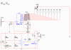
Now in multisim, I have created this simple design. see pic #1
Now if you notice in this schematic I am using a lm339
AD. With this multisim model my design works like a charm. (reason I used LM339AD, it was the only model that worked with my design, all others had a >= 1V output)
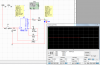
Now pic #2 is of the exact same design but a different multisim model for the lm339. This time I am using the lm339
N model. now as you can see the design fails because no matter the voltage on the non-inverting input of the lm339 the output is ~1.20V. so the transistor is always conducting.
Now as I stated before, I have the ST LM339N chips sitting on my desk. But now I am concerned that my whole design is flawed because I bought the wrong chips(I will be breadboarding this design soon to test the chips). My question to you is this... What multisim model should I be using to represent the ST LM339N chip in multisim? I would think the lm339n is the model I need, but according to digikey, maybe I should be using the lm339
A.
So that brings me to my next question... How do I tell according to the datasheet what model in multisim is the appropriate model to be using? How can I compare the the multisim model to the datasheet to know what I need?
edit: I thought the reason for the N was just the packaging style of the chip(DIP-14), so why do all the multisim models vary so greatly in the output given the exact same conditions for the inputs?
 This should be so simple it's stupid. But someone please tell me what I am doing wrong.
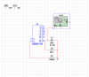
![CropperCapture[1].jpg](/forums/data/attachments/0/432-a5638fc2685f4c074985e4f9bf0ac4c7.jpg)
![CropperCapture[1].jpg](/forums/data/attachments/0/435-dbdee1d2fe424fc674a10a6fcf3943c7.jpg)
![CropperCapture[2].jpg](/forums/data/attachments/0/440-7d0458151b0c41420713b49b41dd2cc4.jpg)