Multisim simulation help

jackorocko

Apr 4, 2010
1,284
Joined
Apr 4, 2010
Messages
1,284
Ah, I see now. What you want to do is arrange some logic to do the latching for you.

You'll need a way to reset it (probably when power is first applied, and at other times as required)

To do this, you should look at flip-flops -- there are many different types, but the very simplest will do the trick for you. Unfortunately you'll have to construct one from a pair of OR gates (4071) but this is trivial to do.

There are flipflops available in packages, but they are generally clocked, so they won't do exactly what you want. Anyway, it's fun to make your own :)

The modification I have suggested you try will eliminate the need for a schmitt trigger, but it's worth doing some research on them anyway.


Ok, so now that we on the same page again. LOL

I got to thinking about your comments on using the LDR as a reset. It made a lot of sense to me and I think I have come up with a better plan then I had before. Instead of holding the MR high, why not just let it oscillate.

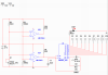
Now I am using an LM339 quad comparator. So it got me thinking, why couldn't I use one bridge and two comparators, hook them up so that when the LDR is 'tripped' the one comparator would reset the 4060(reset the timer to zero) and the other comparator would drive the alarm. I suppose I could use logic gates to do the latching which would overall make the design streamlined instead of a bunch of bulky relays.

does this design model seem plausible? Also, would it still be better to use positive feedback on both comparators or one or none?

Note I haven't figured out the logic gates yet, But with all the possible combinations it shouldn't be that hard, I hope :rolleyes:
 

Attachments

  • trip_alarm_dual_comparator_multisim.PNG
    trip_alarm_dual_comparator_multisim.PNG
    36.7 KB · Views: 3,582

(*steve*)

¡sǝpodᴉʇuɐ ǝɥʇ ɹɐǝɥd
Moderator
Jan 21, 2010
25,510
Joined
Jan 21, 2010
Messages
25,510
I'm not sure what the point would be in having 2 comparators doing exactly the same thing.

I didn't suggest using the LDR as a reset. I thought you were using the LDR to essentially remove the assertion of the reset signal (and then not re-asserted due to the relay holding itself in the on state.

It seems that your original circuit detected a change in light level above (or below) some level and used that to start a counter that would do *something*, and keep doing it regardless of subsequent changes to the light level.

The uncertainty is largely a result of me not recalling exactly what you had planned to so (in a general sense). Did you explain that at the beginning of the thread?

edit: No, you didn't. That explains a lot.
 

jackorocko

Apr 4, 2010
1,284
Joined
Apr 4, 2010
Messages
1,284
The uncertainty is largely a result of me not recalling exactly what you had planned to so (in a general sense). Did you explain that at the beginning of the thread?

edit: No, you didn't. That explains a lot.

I did not explain what I was trying to do here. But a lot of this is because I am having multiple issues, some with the design of the circuit itself and some with the simulation software. which is in part up to the fact that I have no idea where I am going with this since it is my first and only electronics project. I have a beginning point and an end point. The middle is very unclear. My only concern with this whole project is one thing

1. I am able to simulate the whole project from start to end

It seems that your original circuit detected a change in light level above (or below) some level and used that to start a counter that would do *something*, and keep doing it regardless of subsequent changes to the light level.

This is exactly what I am trying to do.

I'm not sure what the point would be in having 2 comparators doing exactly the same thing.

I thought about this too. But I have already bought quad comparators unknowingly because I didn't research the part enough. So I just figured I'd kill two birds with one stone. By using two comparators I could separate the logic IC from the latching relay and also be using up a comparator that would essentially be doing nothing. This is probably poor design, but I wouldn't know as I was never a good designer to begin with.

Now as frustrating as this is to me, I still have a smile on my face and still want to complete this project. So if you have any good ideas or a direction in which I should investigate, please don't hesitate to point me in that direction. As of right now I will look to investigate logic gates to control the latching part of the design.

As always thanks to everyone who takes the time to help me. Without help I would be like a fish out of water.
 
Last edited:

NickS

Apr 6, 2010
367
Joined
Apr 6, 2010
Messages
367
Flip Flop Link: (shows a couple different types)

Schmitt Trigger: See attached picture. (taken from wikipedia)
The wavy line "U" represents your comparator input signal.

The red dashed line represents the comparator reference voltage. so when your signal crosses the red dashed line you would expect the output of the comparator to look like the shaded section "A"

The green dashed lines represent hysteresis which is basically a dead region. By that I mean the output does not transition unless the input signal is beyond the green dashed lines(higher or lower). This can be seen from the shaded section B

The advantage of a schmitt trigger(which is just a comparator with hysteresis) is that you don't have rapid back and forth transitions when the signal approaches the reference level. In most all cases you want at least a little bit of hysteresis. Also notice that hysteresis adds delay to the output.

And I heard the magic word "car" in one of your previous posts. Have you taken precautions to ensure that your system will be safe from the associated transients that come with automotive electronics?
glance through this
 

Attachments

  • ST.png
    ST.png
    47.2 KB · Views: 558
Top