Sir ido . . . . .
Taking your photos and evaluating . . . . here is what my learned eyes are perceiving . . . .
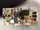
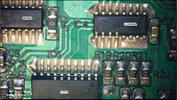
On my markup placed just below, lets initially inspect a questionable area on the first photo, and its being specifically located at center board area, between the two marked in solder blobs/pads with BLUE triangles. NOW, is that being a hoz foil fracture, crossing an arc between those 4 pads ?
My two double RED and BLACK circles are on a zener diodes connection that relate to a voltage reference feedback to the 4 pin 817 family of optical isolater that determines 12 V supply voltage regulation. . . . . along with its derived 5V sub supply.
If that questionable drop down foil appendage is opened, the diode negative lead floats.
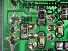
Sooooooo . . . . get metering and put into low ohms function and meter between the BLACK double circled pad and any of the . . .at least 5 . . . connections that are common with the top of that R16 47K SM reee-sistor.
Then hold probes in place with 1 hand and grab the large EC2 cap and exert pressure towards both chassis sides . . . . . PARTICULARLY towards the AC HOT LINE markings side, to then see if an opening connection occurs.
If there is being no lateral micro cracking of the LESS than paper thickness foil, we can now continue.
So o o o o o o o it looks like both your main 12 VDC supply and 7805 derived 5 VDC supply are being present.
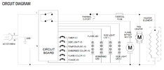
In "reading the board" I can see that the major RL1 relay at the top is responsible for switching AC power to the units heater element . . .see the bold RED arrow and its contact action.
Additionally the mid position-minor relay RL2 feeds power to a motor by its bold RED arrows contact action.
Finally, the end position 2nd minor relay RL3 feeds power to a fan by its bold RED arrows contact action.
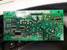
In looking at the 3 principal I.C.'s used, I saw the need for the relays to
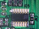
u Processor handshaking and ascertained that the right top I.C. must be of the ULN2xxx series of 7 darlington transistor sets.
See its details from my bottoms two add ons.
From a look at its pin 8, I see it being grounded . . . . along with a libbbbbbbbbberal lateral big blob of solder, which is then also grounding out its unused inputs.
Pin 9 receives 12VDC power.
Then there are being 3 unused output connections and then pin 13 output feeds down to
BLUE square terminal /coil of HEATER relay.
Pin 14 output feeds to
VIOLET square terminal /coil of MOTOR relay.
Lastly Pin 15 output feeds to
YELLOW square terminal /coil of FAN relay.
End Pin 16, must also be unused.
On the input side I am seeing R??R??R?? and fer dern sure, R22 SM resistors that receive on off commands from output ports of the units 20 pin custom
u Processor chip.
My educated guess is that the 4th input port is giving the option of fan only use vice the combination, being used in HEATING mode.
HOWTOMAKEANDDOTEST-EE-TEST-EEANDTHEREBYBEMAKINGYOUEVERSOMOREWORLDLYEDD-U-CATED . . . . .
I have 4 BROWN squares marked at the inputs of the ULN2003 driver, we will now test relay actions via them.
If there is no separate master power switch, we can assume that the little switch mode power supply used in this unit will be running for a full
26 11/17ths hours a day . . . . . . if the unit is being plugged into AC power . . . . . so that your remote control will be 100% time responsive.
If that is CN5 that has a 5 pin connector affixed on one end of its multi unused pins, go to the +5 end pin and to the foils solder side and solder tack on the end of a flying wire . . with such excess . . . that it can reach as far as the relays. A 1 k resistor gets soldered on its wire end.
You now probe with that free resistor end.
With the board AC connected . . . . . but no need of the plug in units . . . . . confirm that +5VDC.
If being present, then you can touch the
BROWN square input resistors, with that probe resistor, and expect a respective relays click sound at each one.
I can't POSITIVELY confirm the "R22" series of values but expect the image blur reads 470 or 4700 ohms.
Try your probe resistor at both ends of a "R22" resistor for certainty.
If all of the inputs give audible relay clicks . . . . . or hand feel able mechanical vibrations. . . . . then
ON WITH THE SHOW !
Considering, that the previous testing confirmed and made all relays go click-ee click-ee !
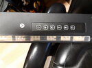
Consider, now, additionally having the plugs also connected, that are being circuit related to the units remote control as well as its manually controlled push buttons panel .
Take voltmeter in hand and clip lead connect negative probe test lead to a ground . . . . easy, if being near where you read the 5 V test supply.
Take positive meter probe and individually test each of the bottom sides of the "R22" resistors.
As you go thru all of the manual push buttons possibilities or via remote, one should produce an activating voltage presence to the port being monitored.
Its telling you that the
u Processor is outputting a turn on voltage to that relay function.
FOTIE-GRAF . . . . . .a l l l l l l l l l marked up . . . . . ( On mousie . . . .
TWO LEFT click-ee click-ee's . . . . makes
much-much 'mo
BIG-
BIG-ee)
BREAK-BREAK and FEED BACK(sack) time . . . . .
Lastly . . .how about the numbering on the two other I.C.s . . . . . I'm expecting the far left to be interfacing from other u Processor output ports to the transistors on the left and them then powering the resultant LED lighting
GLAMORAMA !
73's de Edd . . . . .
Considering how Amazon tends to "Overpack"
To save some BIG money on a coffin, just order and buy a ball point pen from Amazon . . . . and then, you just re-use the box it will come in.
.