New to this site with a (possibly) complex question

DanFraser

Sep 27, 2011
9
Joined
Sep 27, 2011
Messages
9
Hi, new to these forums!

Pretty much everyone has seen the tape adapters for MP3 players, iPhones and other devices to play audio through a cassette player in a car. I have one, except I want to get 'freaky' with how it works. How would I go about wiring the cable that is on the adapter directly into the radio cassette? My idea is to hide the cable very discreetly up to a discreet mounting point for my iPhone, the cable going directly into the player and the unit activated to play the audio input by inserting a blank tape. This whole thing is about the look, the cassette player is original and is intended to follow the theme of my car of looking factory standard but have little modern upgrades. I've done quite a few things that never existed on the car I have and this one of the little touches I'm after. I can supply pictures and texts of what's written on the chips in the player if required!

Thanks for reading and I hope you can help!
 

davenn

Moderator
Sep 5, 2009
14,478
Joined
Sep 5, 2009
Messages
14,478
hi Dan
Welcome to the forums

Yes it is possible ... do you still want the cassette player to function tho ?
a circuit diag for the model of the radio/cass. player would be really helpful
do some googling on the make and model of your unit and see what you can find.
from that we could get you on the right track :)

cheers
Dave
 

DanFraser

Sep 27, 2011
9
Joined
Sep 27, 2011
Messages
9
Thanks for replying.

As long as the radio still works I'm not fussed as I have no tapes at all. If I'm able to disconnect power to the tape deck that'd be nice to stop the quiet whirring going on.

I'll start hitting up some searches tomorrow as it's late.
 

DanFraser

Sep 27, 2011
9
Joined
Sep 27, 2011
Messages
9
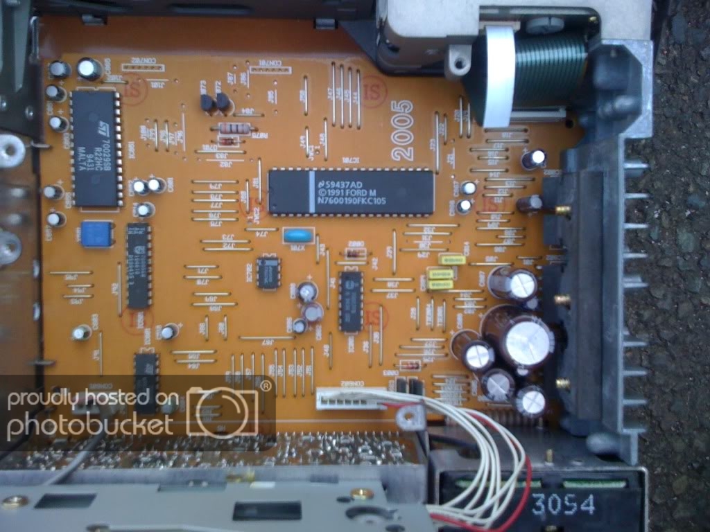
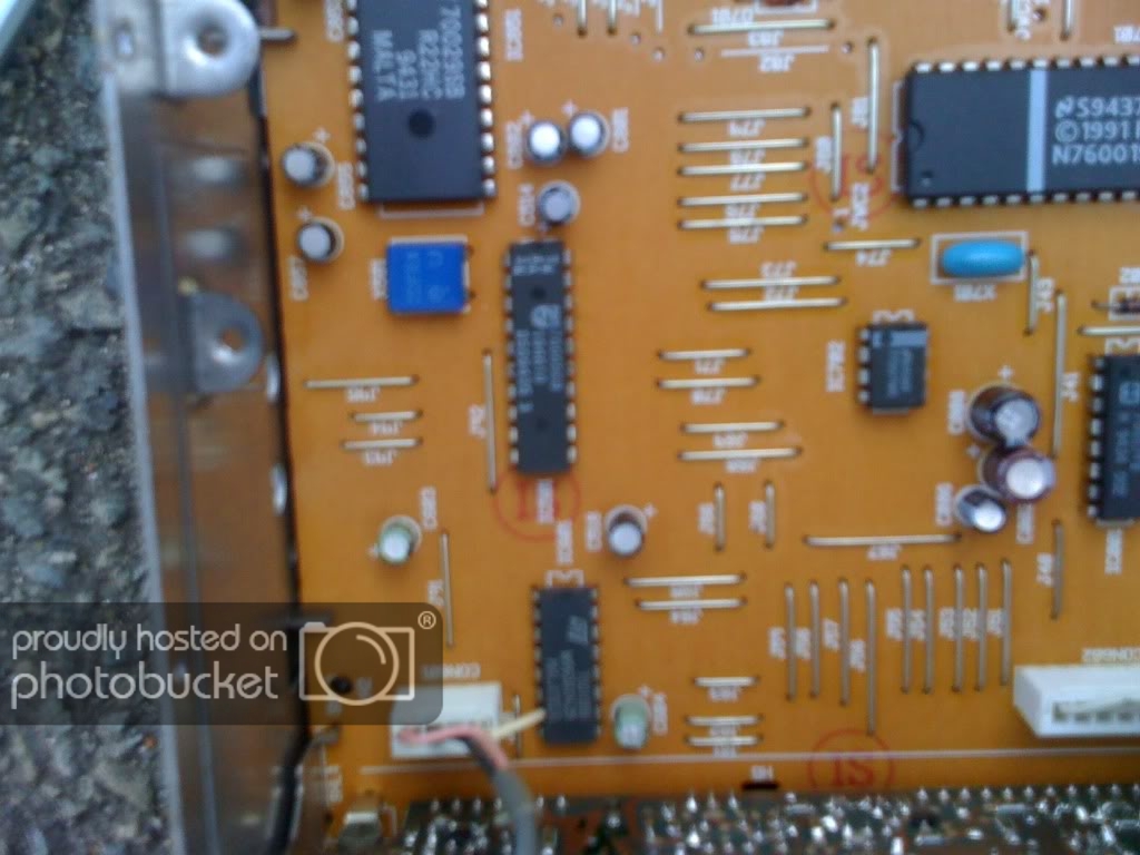
Ok, googling is an absolute pain. I do have some pictures of the internals after wondering about this many months ago and thought I'd take them just in case.

IMG_0697.jpg


IMG_0699.jpg


IMG_0700.jpg


IMG_0701.jpg


IMG_0702.jpg


The two white connectors (CON601 and CON602, but the zero's do look like an 8 in the pic) at the bottom both go into the tape deck mechanism. In the first pic the tape deck mechanism is basically removed and stood on it's side on the edge of the unit casing. The grey wrapping on CON601 does remind me of the audio wiring in some other things I've seen (CD audio wires in a computer to the sound card).
 

DanFraser

Sep 27, 2011
9
Joined
Sep 27, 2011
Messages
9
I haven't taken the radio out yet to confirm, but a volvo forum has given hints at soldering connections to CON601 with the black red and white connectors, then snip the red on CON602 to kill the motor!

Is there a way to test the left and right channels of this theory? Leave it plugged in but open cased and maybe use a battery to short the signal to make noise?
 

davenn

Moderator
Sep 5, 2009
14,478
Joined
Sep 5, 2009
Messages
14,478
hi Dan,

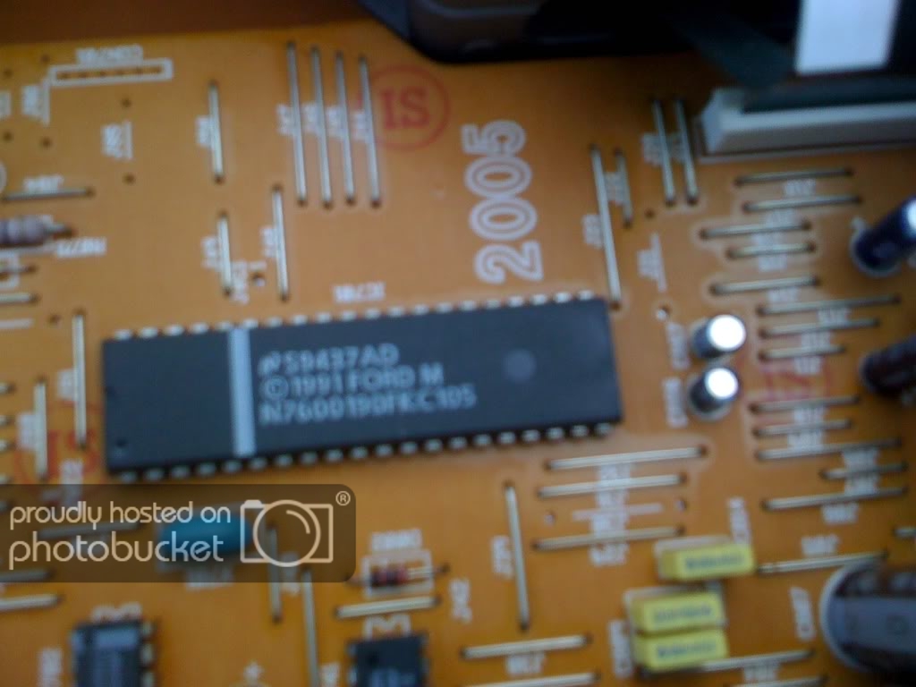
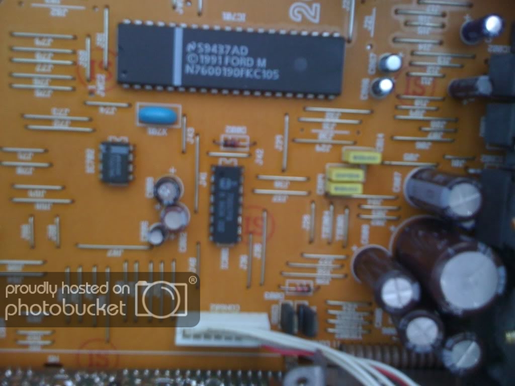
unfortunately, the last 3 pics are a bit too blurry to get any real info from

can you confirm that that grey shielded wire in the lower left actually goes to the tape head please
DONT put ant power across those wires, you will kill the preamplifier. That tape preamp will be too sensitive for a MP3 player input we will need to insert the MP3 signal further up the line. Hence why we really need a cct diagram to see what those chips are and when we can connect a signal into.
What is the make and model of the unit and I will also try some googling.

cheers
Dave
 

davenn

Moderator
Sep 5, 2009
14,478
Joined
Sep 5, 2009
Messages
14,478
ok, hmmm google not much help in that case huh. was sorta hopeing that it had a more well known brand of radio cass player :) plenty of sites offering radio coding info

ok I assume you still have that cassette unit that pops into the player that the MP3 player plugs into ?
I did own one of those many years ago, not sure how much circuitry is inside on of those. what Im thinking is maybe we could dispense with the tape head part that is in that cassette and hard wire the cable that goes to it directly to the cable coming from the tape head in the player.... namely that grey covered twin screened lead.

That cassette interface unit should have the appropriate circuitry to match the output from the MP3 player to the tape deck.
You may be able to rehouse that circuit into a smaller plastic box with a cable in and a cable out to a plug that can be plugged into a socket etc on the cassette player

Dave
 

DanFraser

Sep 27, 2011
9
Joined
Sep 27, 2011
Messages
9
Well I opened up the player again, and wrote down all the details of all the chips located in there.

Code:
ST   70010BB
   W993A9435      [I][B](16 pin, labelled IC601)[/B][/I]
    MALAYSIA

Code:
T          70005EB
AW          194610       [I][B](20 pin, labelled IC501, made by Philips)[/B][/I]
IA       DSD9435 3
 N

Code:
ST    70029SB
        R22HC        [I][B](28 pin, IC 851)[/B][/I]
         9431
        MALTA

Code:
B45AD          [I][B](This is the EEPROM, thank you google translate, lol)[/B][/I]
77007MC

Code:
B    70017FB       [i][b](16 pin, IC001)[/b][/i]
  H 9434 002

Code:
       S9437AD
   1991 FORD M    [I][B](This is very easy to find to buy but no info on it)[/B][/I]
N7600190FKC105    [I][B](IC701, 40 pin)[/B][/I]

I've been trying to find info on these, but having no luck, for example alldatasheets has nothing about these.
 

DanFraser

Sep 27, 2011
9
Joined
Sep 27, 2011
Messages
9
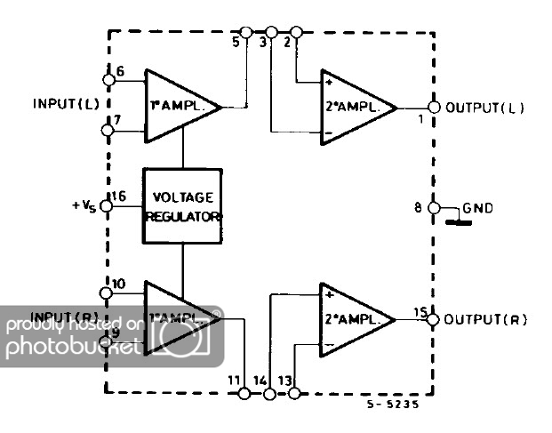
Looks like I've found the pre-amp. I know this has to be bypassed in the case of the tape player to line input conversion as the audio is already boosted by the iPhone itself and other people have already reported blown stereos, speakers, car looms etc. So all I have to do apparently is intercept the outputs from these.

Here's the schematic:

TDA3420.jpg


So from what I can tell, solder onto the very easy to get wires (yeah, not PCB on this section in this radio!) and cut the section between my solder joints and the IC.

I just ened to remove the radio again, and confirm the inputs of the IC are from the tape deck.
 

davenn

Moderator
Sep 5, 2009
14,478
Joined
Sep 5, 2009
Messages
14,478
yup you could cut PCB tracks leaving pins 1 and 15 of that chip. That is after confirming that the radio doesnt get pre-amped with that chip as well.

report back and let us know what you find :)

Dave
 
Top