Old board schematics

roughshawd

Jul 13, 2020
616
Joined
Jul 13, 2020
Messages
616
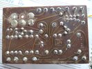
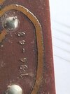
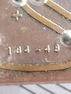
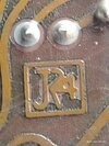
There was once an old electrician technician who made wah wah pedals for sale. His initials were probably JR, and he was building his fourth wah wah. There was such a demand for his pedals that he hired out to a big company named regal to make a bunch of different wah wahs, some that had fuzz boxes and other effects built in. His board #134-43 went in the do-wah-diddy pedal. After a long time the pedal stopped working and was tossed in the pile with the other 'broken' pedals. Years later, the pedal was salvaged by a millennial who was about to throw it away, and then thought his aging friend might want it. When it didn't work the old entertainer threw it in the garbage, where some person salvaged it again... It went from collector to collector across the city, and ended up in a junk box at an auction sale where this roughshawd handyman found it. The handyman knew they usually keep records of these boards, and decided to ask if anyone might know where he could get a schematic of the jr4 #134-43 board and a wiring diagram for a Regal Do-Wah-Diddy Wah Wah Pedal.
 

Attachments

  • 1737141313706145922467640691237.jpg
    1737141313706145922467640691237.jpg
    352.9 KB · Views: 12
  • 17371413638284704752003095526978.jpg
    17371413638284704752003095526978.jpg
    205.7 KB · Views: 12
  • 17371413991936779442175506263978.jpg
    17371413991936779442175506263978.jpg
    181.6 KB · Views: 10
  • 17371414299365247488460087002745.jpg
    17371414299365247488460087002745.jpg
    199.3 KB · Views: 12

roughshawd

Jul 13, 2020
616
Joined
Jul 13, 2020
Messages
616
What does IOP on a board mean?
 

Attachments

  • 17371508475677599835730232019545.jpg
    17371508475677599835730232019545.jpg
    362.8 KB · Views: 13

danadak

Feb 19, 2021
1,063
Joined
Feb 19, 2021
Messages
1,063
Some solder problems :

1737202630997.png

Bottom pin 2'ond one in from left.

1737202716436.png

Top right pin.

1737202826742.png

Top right 3 pins.

Pics of top of board ?
 

roughshawd

Jul 13, 2020
616
Joined
Jul 13, 2020
Messages
616
Reflowed. Found out of spec caps, transistors in backwards, wrong resistors. I didn't have the right time caps... Got close though!
 

Attachments

  • 17375951274855564350902053021308.jpg
    17375951274855564350902053021308.jpg
    347.5 KB · Views: 10
  • 17375951610584827130047534366561.jpg
    17375951610584827130047534366561.jpg
    514 KB · Views: 10

roughshawd

Jul 13, 2020
616
Joined
Jul 13, 2020
Messages
616
Original JR4 regal do-wah-diddy board... To bad there's no fuzzy blue or red box!!
 

Iron Works

Apr 24, 2026
1
Joined
Apr 24, 2026
Messages
1
Just so you know, I have the exact same PCB board JR4 134-43 in a wah pedal labeled Foxx Wah & Volume. The potentiometer has been replaced so I'm unable to date it but almost certainly 1970s. I believe the same manufacturer issued their wah pedals under various brands including Foxx, Regal, Heil, Footsystem, etc.
 

AnalogKid

Jun 10, 2015
3,045
Joined
Jun 10, 2015
Messages
3,045
Single-sided and only 25 components. If you know which ends are the input and output, this is not a difficult schematic to reverse. To start, print the bottom side image mirror-image, and start marking up a blown-up image of the top side with traces. To keep the board design single-sided, there are lot of long traces looping around things. Step 2 is to redraw the traces with more straight-line connections to eliminate all of that looping clutter. Now you have something you can transfer to paper. All of that is less than 1 hour.

What are the markings on the transistors?

ak
 

AnalogKid

Jun 10, 2015
3,045
Joined
Jun 10, 2015
Messages
3,045
Yeah, but I didn't see an actual answer in the thread, and he's still around.

ak
 
Top