Panel Heater Power Board repair

FIIIP

Feb 26, 2026
12
Joined
Feb 26, 2026
Messages
12
Hello,

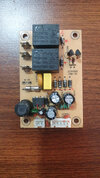
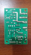
I have this power board that use chinese PN8024R regulator to output 12V, but instead outputting 12V it outputs like around 28v to 50V.
If anyone have any idea what could be wrong, please let me know. Here is the thread from another forum: https://forum.allaboutcircuits.com/t....208572/page-4

Thank you!
 

Attachments

  • 20251031_151307.jpg
    20251031_151307.jpg
    279.8 KB · Views: 8
  • vol1.jpg
    vol1.jpg
    382.5 KB · Views: 8

mechtronics

Aug 7, 2011
164
Joined
Aug 7, 2011
Messages
164
Yes, they were fine, but I replaced them anyway
what about all other components? capacitors? inductors? etc and how did you check them? did you physically desolder them and take them out and check them? and another thing to point out is a lot of switch mode power supplies use feedback so when a load is connected to it the output voltage stabalizes. under no load voltage will be higher than usual. under load voltage stabalizes. when you have something connected to the output use a digital multimeter to check what the voltage is when load connected to output.
 
Last edited:

bertus

Moderator
Nov 8, 2019
3,835
Joined
Nov 8, 2019
Messages
3,835
Hello,

Did you have a look at the datasheet?

Bertus
 

Attachments

  • PN8024R.pdf
    1.2 MB · Views: 2

FIIIP

Feb 26, 2026
12
Joined
Feb 26, 2026
Messages
12
what about all other components? capacitors? inductors? etc and how did you check them? did you physically desolder them and take them out and check them? and another thing to point out is a lot of switch mode power supplies use feedback so when a load is connected to it the output voltage stabalizes. under no load voltage will be higher than usual. under load voltage stabalizes. when you have something connected to the output use a digital multimeter to check what the voltage is when load connected to output.
Yes, I have desoldered all components, and checked them, here is the list.

@bertus Yes,I have checked it, I am not building their rtypical usage scenario with these components to see how it will behave.
1772190831543.png
 

FIIIP

Feb 26, 2026
12
Joined
Feb 26, 2026
Messages
12
When I have control board connected, it burns AMS117 3.3V... and contorl board beeps repeadetly fast, but when i check after AMS117 its shorted... i replaced it a couple of times.. Control board works fine on 9V battery when connected(and AMS117 is new)...
 

mechtronics

Aug 7, 2011
164
Joined
Aug 7, 2011
Messages
164
When I have control board connected, it burns AMS117 3.3V... and contorl board beeps repeadetly fast, but when i check after AMS117 its shorted... i replaced it a couple of times.. Control board works fine on 9V battery when connected(and AMS117 is new)...
is there a feedback resistor to the comp pin 3 of the IC?
 

FIIIP

Feb 26, 2026
12
Joined
Feb 26, 2026
Messages
12
This outputs 15V... instead of 4.7uF/25V i put 10uF/50V because I dont have 4.7/25V, and instead capacitor 333, i put 2A223J green capacitor
 

Attachments

  • 20260227_123345.jpg
    20260227_123345.jpg
    367 KB · Views: 4

FIIIP

Feb 26, 2026
12
Joined
Feb 26, 2026
Messages
12

Attachments

  • 20251030_153635.jpg
    20251030_153635.jpg
    481.4 KB · Views: 2
  • 20251030_190612.jpg
    20251030_190612.jpg
    348.3 KB · Views: 2
  • 20251031_151259.jpg
    20251031_151259.jpg
    330 KB · Views: 2
  • 20251031_151307.jpg
    20251031_151307.jpg
    279.8 KB · Views: 2

FIIIP

Feb 26, 2026
12
Joined
Feb 26, 2026
Messages
12
The two caps before the PN8024R are each 8.63uF(I guess this is together since they are connected in circuit), in circuit, for reading off the circuit, there is a table above I already sent
 

mechtronics

Aug 7, 2011
164
Joined
Aug 7, 2011
Messages
164
the capacitor on pin 3
The two caps before the PN8024R are each 8.63uF(I guess this is together since they are connected in circuit), in circuit, for reading off the circuit, there is a table above I already sent
what about cap connected to comp pin 3
 

FIIIP

Feb 26, 2026
12
Joined
Feb 26, 2026
Messages
12
The green one is 22uF i tried replacing them with 22nK100, but that didn't solved anything
 

mechtronics

Aug 7, 2011
164
Joined
Aug 7, 2011
Messages
164
The green one is 22uF i tried replacing them with 22nK100, but that didn't solved anything
i can see in the picture that you are missing an AC Neutral terminal where is that? you have AC Live and AC live out and AC neutral out.
 

FIIIP

Feb 26, 2026
12
Joined
Feb 26, 2026
Messages
12
i can see in the picture that you are missing an AC Neutral terminal where is that? you have AC Live and AC live out and AC neutral out.
Oh, you mean on the board, it got desoldered when i was unpluging the wire, I soldered it back :)
 

FIIIP

Feb 26, 2026
12
Joined
Feb 26, 2026
Messages
12
This outputs 15V... instead of 4.7uF/25V i put 10uF/50V because I dont have 4.7/25V, and instead capacitor 333, i put 2A223J green capacitor
So, I replaced 2k resistor with 1k resistor, and now its outputting 12.3V...
 
Top