Phillips TV just died 42PUS7809/12

Frag-Mast3r

Dec 26, 2022
3
Joined
Dec 26, 2022
Messages
3
Hello dear readers,

my TV turned off while I was watching and I can't turn it on anymore. There is no power/standby LED or any sign of life.
My guess is, that there is a problem with the power supply.
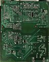
I took pictures of the mainboard (green) and PSU (brown).
On the mainboard I didn't see anything that looks faulty but on the PSU I saw a part where the circuit board is dark. Maybe there was a discharge or something like that.
Unfortunately I couldn't find a replacement for the PSU (FSP104-4FSO1).
My Questions are:
- Could the part in the picture be the reason for my tv not working anymore?
- If yes: What kind of part is it?
- Can you help me identify this part to by a replacement?

Thanks in advance :)

PS. The service manual was to big to upload so here is the link:

IMG_0505.jpegIMG_0506.jpegIMG_0507.jpegIMG_0503.jpeg
 

kellys_eye

Jun 25, 2010
6,512
Joined
Jun 25, 2010
Messages
6,512
If you test D501 it will likely show a short circuit but that will probably have been as a result of U501 going faulty too. Possibly other issues as well but those would be the two starting places.

It might be easier and more cost-effective to seek a replacement board.
 

Frag-Mast3r

Dec 26, 2022
3
Joined
Dec 26, 2022
Messages
3
If you test D501 it will likely show a short circuit but that will probably have been as a result of U501 going faulty too. Possibly other issues as well but those would be the two starting places.

It might be easier and more cost-effective to seek a replacement board.
Thanks for the fast reply :)
Would you say it’s only the psu, not the mainboard? I found a replacement that I could order from Poland. But I just want to be sure that it will work with a new psu board.
I’m a noob about circuit boards that’s why I need a second opinion ;-)
 

kellys_eye

Jun 25, 2010
6,512
Joined
Jun 25, 2010
Messages
6,512
Very unlikely (imo) the fault spread to the other board. Never any guarantees though....... but it's rare.
 

73's de Edd

Aug 21, 2015
3,730
Joined
Aug 21, 2015
Messages
3,730
Sir Frag-Mast3r

I did not find a power supply schematic of that unit in any of that tech referencing that you supplied.
But I can see that your nasty diode is on the HOT AC line powered side of your T501 Stand By power
supply that is built up with the FSB117 -U501 . . . . . ." power supply in a chip".
It runs ALL of the time that the set is plugged into an A.C. line and HAS to be working in order for the other larger power supply
. . . . . .with its much LARGER power transformer . . . . . to power up.
With no schematic being provided, I supply that basic design of the circuitry that the FSB117 uses in its Application Design Note.
Give us as good of a photo, as you provided of the componet side . . . . . . . but centered upon the foil trace side and then its " schematic" can be read off from its foil traces.
In initially analyzing, for your measuring, use both low ohms and diode Voltage Forward tests of D501. Also expect to pull one of its lead
ends out of the circuit board, if you get bonkers readings.
R505 seems to be of a 10' ish ohms value, so see if it is reading good ohms presence or, if being open circuit . . . . but with the pair being on the side of the IC U501 that feeds the primary of T501, I actually suspicion them to be a snubber pair. (Need those foil pics)
Both power supplies derive their RAW DC supply voltage from long black C601 E-cap at center bottom .
I feel that it branches over to pinkish R621--R671 ?, which color bands out as being another low ohmmic value resistor.
Confirm that it is not open.

Check and see if the voltage output section of that T501 . . .the top half . . . . is using a parallel pair, set of diodes D201 and D202
to create its probable 5'ish volts supply that then goes to the right sides extreme dark green E-cap C201 ? then up and thru L2?? 7 turn choke coil and then out of it, over to the C211 companion cap and then the supply goes up to the WHITE connector above them.
If those caps are DC voltage rated at 12VDC we might suspicion that this is being a +5VDC supply.
If 25 VDC rated , it will be a higher supply voltage or if the D201 and D202 are not found being paired up, we may have two different supply voltage outputs.
(But that pi filter inductor wants me to be suspicioning this as being a doubly filtered, single supply.)
Additionally the rightmost of the (3) 817 optical isolators would be the one associated with this SBY supply.

After initial "kick start" I percieve that a parasitic winding of T501 provides voltage then to be rectified byD504 and then filtered by E-cap C512 or its companion to its side, to keep U501 running. ( DDD and CDD on the app note sheet, )
The very first test to do is to connect all plugs and connectors, in order to have a working set and then connect AC power to the set to see if you have raw DC across lo o o o o o o ong black C601 filter.
If so, " ALL" of he parts you see in the whole bottom left quadrant are working, to be able to get that basic supply to you.

Manufacturers Working Circuit . . . . . as . . . . . Sourced from their Application Note . . . . .
1672137916356.png

Standing by for FOIL side "Schematic" Photo and your requested metering findings . . . . . . . .
EatingPopcorn.jpg


73's de Edd . . . . .

Today a man knocked on my door and asked for a small donation towards the local swimming pool . . . . . . hence . . . . . . I gave him a full glass of water.


.
 

Frag-Mast3r

Dec 26, 2022
3
Joined
Dec 26, 2022
Messages
3
Sir Frag-Mast3r

I did not find a power supply schematic of that unit in any of that tech referencing that you supplied.
But I can see that your nasty diode is on the HOT AC line powered side of your T501 Stand By power
supply that is built up with the FSB117 -U501 . . . . . ." power supply in a chip".
It runs ALL of the time that the set is plugged into an A.C. line and HAS to be working in order for the other larger power supply
. . . . . .with its much LARGER power transformer . . . . . to power up.
With no schematic being provided, I supply that basic design of the circuitry that the FSB117 uses in its Application Design Note.
Give us as good of a photo, as you provided of the componet side . . . . . . . but centered upon the foil trace side and then its " schematic" can be read off from its foil traces.
In initially analyzing, for your measuring, use both low ohms and diode Voltage Forward tests of D501. Also expect to pull one of its lead
ends out of the circuit board, if you get bonkers readings.
R505 seems to be of a 10' ish ohms value, so see if it is reading good ohms presence or, if being open circuit . . . . but with the pair being on the side of the IC U501 that feeds the primary of T501, I actually suspicion them to be a snubber pair. (Need those foil pics)
Both power supplies derive their RAW DC supply voltage from long black C601 E-cap at center bottom .
I feel that it branches over to pinkish R621--R671 ?, which color bands out as being another low ohmmic value resistor.
Confirm that it is not open.

Check and see if the voltage output section of that T501 . . .the top half . . . . is using a parallel pair, set of diodes D201 and D202
to create its probable 5'ish volts supply that then goes to the right sides extreme dark green E-cap C201 ? then up and thru L2?? 7 turn choke coil and then out of it, over to the C211 companion cap and then the supply goes up to the WHITE connector above them.
If those caps are DC voltage rated at 12VDC we might suspicion that this is being a +5VDC supply.
If 25 VDC rated , it will be a higher supply voltage or if the D201 and D202 are not found being paired up, we may have two different supply voltage outputs.
(But that pi filter inductor wants me to be suspicioning this as being a doubly filtered, single supply.)
Additionally the rightmost of the (3) 817 optical isolators would be the one associated with this SBY supply.

After initial "kick start" I percieve that a parasitic winding of T501 provides voltage then to be rectified byD504 and then filtered by E-cap C512 or its companion to its side, to keep U501 running. ( DDD and CDD on the app note sheet, )
The very first test to do is to connect all plugs and connectors, in order to have a working set and then connect AC power to the set to see if you have raw DC across lo o o o o o o ong black C601 filter.
If so, " ALL" of he parts you see in the whole bottom left quadrant are working, to be able to get that basic supply to you.

Manufacturers Working Circuit . . . . . as . . . . . Sourced from their Application Note . . . . .
View attachment 57495

Standing by for FOIL side "Schematic" Photo and your requested metering findings . . . . . . . .
EatingPopcorn.jpg


73's de Edd . . . . .

Today a man knocked on my door and asked for a small donation towards the local swimming pool . . . . . . hence . . . . . . I gave him a full glass of water.


.
Hello 73's de Edd,

thank you for your detailed reply. I feel a bit bad, because I followed kellys_eye advice and ordered the replacement board from Poland before you replied. It just arrived today and the TV is working again :)
But I think your conclusions were right. I attached the foil side where you can see the schematic very clear.
As far as I can tell, its indeed based on the FSB117H application circuit.
To be honest. I'm a total noob about electrics and circuit boards. But I ordered a multimeter from amazon and measured R505 and it is 10 ohms like you said. Also D201 und D202 are parallel. I think I will study this PSU further and try to learn more about electric circuits because it's very interesting to me.

@kellys_eye
Thank you too for your help.

I wish you two a happy new year.

kind regards,

Frag-Mast3r
 

Attachments

  • IMG_0515.jpeg
    IMG_0515.jpeg
    515.4 KB · Views: 5

kellys_eye

Jun 25, 2010
6,512
Joined
Jun 25, 2010
Messages
6,512
Hello 73's de Edd,

thank you for your detailed reply. I feel a bit bad, because I followed @kellys_eye advice and ordered the replacement board from Poland before you replied. It just arrived today and the TV is working again
It's always interesting and satisfying to locate and repair a circuit to component level - it's a skill set that is sadly in decline these days. That said, the KISS principle applies too (keep it simple, stupid) and replacing the board to get the set working is far quicker than learning the repair process (and ordering spares etc) and my have kept you entertained over the holidays (in the literal sense).

Glad to know it's been fixed though. Follow Edd's advice by all means as it's very detailed and he can talk you through the process and help you learn a lot.
 
Top