@Gryd3
Ok, but right now i dont have a multi-meter but when i have access to one i will do what is needed and reply back to you. Also are you saying if i just have the right voltage divide in the potentiometer then the circuit would work in the way i want it to.
Not quite. We will be looking at this in stages.
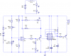
The comparator 'IC3' is doing the the work in toggling logic on/off depending on the LDR. If that works fine, we explore the output side of that to make sure the transistor and everything behind it is setup properly.
The - Input on IC3 should be 4.5V based on the schematic.
The + Input varies... and based on the schematic, I think the incorrectly wired potentiometer might be to blame... but we should always confirm before jumping to conclusions
")
You can of course try to bypass POT1 to see what happens. Please don't accidentally bypass R13 when you do this though.
Ideally... what should happen here, is when the Comparator output is 'high', it should be lighting up D4. And at this time Q3 should be off so there should be no current through D2.
When the Comparator output is 'low', the transistor (Q3) should turn on which will bypass D4 (turning it off) and providing a path for current to flow for D2 (turning it on). While at the same time, the 555 timer 'trigger' gets toggled which will set off the buzzer.
We know how it 'should' work, just need to test to make sure.
We can blindly swap out parts and change something, but what if a part is damaged that is causing the problem?