Possible to modify LED Christmas tree circuit for dimming?

bobc

Jul 31, 2011
7
Joined
Jul 31, 2011
Messages
7
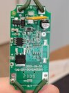
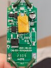
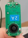
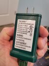
The LED Christmas tree bought from Walmart is too bright. I'm an electronics hobbyist, so I wouldn't have much trouble modifying the circuit, if I knew what to do, or, if it's even possible, to add a pot or other components, for dimming it. Please have a look at the images and let me know if you see a way to dim it.

Thanks!
 

Attachments

  • 20241213_141028.jpg
    20241213_141028.jpg
    276.2 KB · Views: 7
  • 20241213_141114.jpg
    20241213_141114.jpg
    263.2 KB · Views: 5
  • 20241213_141144.jpg
    20241213_141144.jpg
    221.7 KB · Views: 6
  • 20241213_142345.jpg
    20241213_142345.jpg
    251.5 KB · Views: 7

Bluejets

Oct 5, 2014
7,374
Joined
Oct 5, 2014
Messages
7,374
You could try using a small pwm control on the low voltage output to the LEDs .....BUT.....the LEDs might not like the outcome (flickering etc. or too low a voltage for the LEDs to work at all.

There are small speed controls about $3 on ebay etc. but they are limited to around 12v in......you would need at least 35v input.

Use some bluetack over each LED instead.:)
 

bobc

Jul 31, 2011
7
Joined
Jul 31, 2011
Messages
7
You could try using a small pwm control on the low voltage output to the LEDs .....BUT.....the LEDs might not like the outcome (flickering etc. or too low a voltage for the LEDs to work at all.

There are small speed controls about $3 on ebay etc. but they are limited to around 12v in......you would need at least 35v input.

Use some bluetack over each LED instead.:)
Thanks for the idea, I will think about the PWM control. Maybe I could incorporate an Arduino for this. Most of my electronics experience is working with Arduino/ESP32 boards, instead of dedicated circuits.

It's a five mode device where two of the modes increase brightness from OFF to full ON over three, and five, seconds. To achieve the brightness cycling, are they using a Relaxation Oscillator circuit with the OpAmp? I don't have much experience with OpAmps, but I'm thinking the combination of the resistors and caps determine the cycle rate and LED intensity. It's probably not as simple as using different R and C values, right? Or, replacing one of the resistors with a pot?
 

Bluejets

Oct 5, 2014
7,374
Joined
Oct 5, 2014
Messages
7,374
No requirement for any uc.
As far as the rest, who knows, you have it in your hand not me here.
 

Minder

Apr 24, 2015
3,561
Joined
Apr 24, 2015
Messages
3,561
Thanks for the idea, I will think about the PWM control. Maybe I could incorporate an Arduino for this.

It's a five mode device where two of the modes increase brightness from OFF to full ON over three, and five, seconds. To achieve the brightness cycling, are they using a Relaxation Oscillator circuit with the OpAmp?
I did a similar project for a member of a similar site to this, he had three banks of LED's he wanted a slow phase in phase out of each bank color in turn, so only two banks were actually in action at any one time over the three colors.
I ended up using a small 8 pin PicMicro with Peripheral Pin Select (PPS). And 3 PWM Outputs that would ramp up & down via a timer count
 

bobc

Jul 31, 2011
7
Joined
Jul 31, 2011
Messages
7
I did a similar project for a member of a similar site to this, he had three banks of LED's he wanted a slow phase in phase out of each bank color in turn, so only two banks were actually in action at any one time over the three colors.
I ended up using a small 8 pin PicMicro with Peripheral Pin Select (PPS). And 3 PWM Outputs that would ramp up & down via a timer count
Thanks Minder. I will be creating a replacement controller for the OEM controller. Mine will use an Arduino (probably Every) in conjunction with an IC (type undecided), and pot. I'll use the OEM AC/DC transformer, which puts out 29 VDC as input to my controller. The string of 1000 LEDs pull a max of 2A.
 
Top