PSU advice

darren adcock

Sep 26, 2016
463
Joined
Sep 26, 2016
Messages
463
Why have you gone to the bother of mounting your transformer on a sub chassis?

I'm not sure to be honest.... I think I am over compensating as this is new to me. As I said though all criticism and advice is welcome
 

Harald Kapp

Moderator
Moderator
Nov 17, 2011
14,293
Joined
Nov 17, 2011
Messages
14,293
file:///C:/Users/User/Downloads/Instructable%20-%20Assembling%20a%20series%20lamp%20limiter.pdf
I don't have acces to your C:\ drive and on mine I can't find the pdf ;)
The gry and purple wires are soldered and then shrink tubed (but used clear shrink tubing).
That should be o.k., just not visible on the photos. Just for safety a double insulation (2 layers of shrink tube) is what I recommend.
 

darren adcock

Sep 26, 2016
463
Joined
Sep 26, 2016
Messages
463
I don't have acces to your C:\ drive and on mine I can't find the pdf ;)

That should be o.k., just not visible on the photos. Just for safety a double insulation (2 layers of shrink tube) is what I recommend.
Flippin eck I'm doing well on here today, where's that IT job ;-)

Yes I'll follow your instructions and double insulate, I have grommets on order and will build the Lamp limiter tomorrow.

Thanks!
 

darren adcock

Sep 26, 2016
463
Joined
Sep 26, 2016
Messages
463
Really liking the new look forum! :)

I've been really ill since last spoke here.

I got all the parts for a light limiter circuit. I've been struggling though knowing what to trust on the internet.... seems a lot of different wiring layout etc....Maybe someone has a wiring diagram they can pass my way please?

Here is how i have it wired up at minute (will only plug in after verification here)....

Thankslight limiter.jpg
 

duke37

Jan 9, 2011
5,364
Joined
Jan 9, 2011
Messages
5,364
That looks OK. I put a switch across the light so that I do not have to remove the device when full power is required.
 

darren adcock

Sep 26, 2016
463
Joined
Sep 26, 2016
Messages
463
That looks OK. I put a switch across the light so that I do not have to remove the device when full power is required.

thanks duke.... I've put the bypass in.

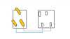
I'm very confused though as I've wired the plug and socket and it appears it has put the to opposite sides? if i was to plug a plug in it now the neutral and live would not match?

I've followed the diagram that came with the plug (wired these plenty of times)... then followed the designators on the inside of the socket.

Here is a diagram to explain further.... wiring check.png
 

(*steve*)

¡sǝpodᴉʇuɐ ǝɥʇ ɹɐǝɥd
Moderator
Jan 21, 2010
25,510
Joined
Jan 21, 2010
Messages
25,510
The lamp should be in the active line.

Connect the Earth too.

If the plug was inserted in the socket of the lead you are making, like pins (i.e. mating pins) should connect.
 
Last edited:

duke37

Jan 9, 2011
5,364
Joined
Jan 9, 2011
Messages
5,364
You have the plug labelled wrongly, looking at the BACK of the plug where the wires are connected, the neutral is on the left. We used to say red to the right but they have changed red to brown which doesn't scan so well.
 

Bluejets

Oct 5, 2014
7,374
Joined
Oct 5, 2014
Messages
7,374
Portable devices should have mains double pole switching.

No idea what the "enclosure" around the transformer is supposed to do.

Earth lug should have a star washer to stop it coming loose.
Actually no idea why there is an "angle lug" at all, can easily break where sharp bend(no radius) has been made.
Black screws not normally used for earth.

Hope there is a terminal and screw to attach the earth and not just looped in like in the photo.
 
Last edited:

darren adcock

Sep 26, 2016
463
Joined
Sep 26, 2016
Messages
463
You have the plug labelled wrongly, looking at the BACK of the plug where the wires are connected, the neutral is on the left. We used to say red to the right but they have changed red to brown which doesn't scan so well.

thanks Duke, I only got to see your reply here late last night and was disbelieving I'd wired the plug incorrectly.... well I eat my hat because you was correct...So used to following wiring diagrams I forget that I can get them wrong.

Got it all sorted now and everything is correct. How do I test it? I read online that plugging it inline with a kettle is a way?
 

darren adcock

Sep 26, 2016
463
Joined
Sep 26, 2016
Messages
463
The lamp should be in the active line.

Connect the Earth too.

If the plug was inserted in the socket of the lead you are making, like pins (i.e. mating pins) should connect.
Hi Steve.

Is the active line "Live"?

Everything is all sorted now following a wiring error from myself
 

darren adcock

Sep 26, 2016
463
Joined
Sep 26, 2016
Messages
463
Portable devices should have mains double pole switching.

No idea what the "enclosure" around the transformer is supposed to do.

Earth lug should have a star washer to stop it coming loose.
Actually no idea why there is an "angle lug" at all, can easily break where sharp bend(no radius) has been made.
Black screws not normally used for earth.

Hope there is a terminal and screw to attach the earth and not just looped in like in the photo.

HI Bluejets, thanks for your reply

The enclosure is there because this is my first build and I have over compensated. I was advise to make sure there was no way the wires from the primary could ever reach the secondary, this was my solution... I can think of easier solutions now.

Do you really think the angle lug to chassis is that much of a problem? I can change it and make a flat lug. But then I see you advise It shouldn't be a lug but a terminal and screw? I can fit a terminal and screw if that is the correct way to do this.
 

Harald Kapp

Moderator
Moderator
Nov 17, 2011
14,293
Joined
Nov 17, 2011
Messages
14,293
I can change it and make a flat lug
I recommend you use a ring cable lug well fitted to the wire and securely screwed to the metal housing.
Without the proper tool the usual crimp connection is not possible. you would have to resort to a soldered or screwed lug. Here are some ideas and tips. Something like the single conductor lug on page 16 is suitable.
 

darren adcock

Sep 26, 2016
463
Joined
Sep 26, 2016
Messages
463
I recommend you use a ring cable lug well fitted to the wire and securely screwed to the metal housing.
Without the proper tool the usual crimp connection is not possible. you would have to resort to a soldered or screwed lug. Here are some ideas and tips. Something like the single conductor lug on page 16 is suitable.
Thanks Harald. I will order this today :)
 
Top