Quad Comparator Help

randyrogers04

Apr 21, 2013
12
Joined
Apr 21, 2013
Messages
12
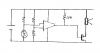
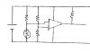
I am currently working on a circuit using a quad comparator. My circuit works but my problem is that output is only putting out 1.3 volts instead of the full 9 volts that is being supplied. My question to you all is what may be causing this and how do i correct it? Thanks in advance for any and all responses.
 

duke37

Jan 9, 2011
5,364
Joined
Jan 9, 2011
Messages
5,364
What is the comparator that you are using and what is the circuit?

Comparators often do not have the facility to pull up the output. They need to have a resistor from output to Vcc.
 

randyrogers04

Apr 21, 2013
12
Joined
Apr 21, 2013
Messages
12
I am using a LM339N quad comparator and my circuit is a basic laser trip wire. Using a photo resistor on the Negative side i am able to turn the power off for the output when it is being hit by the laser beam. When i use my multi-meter to test the voltage, i am getting roughly 8.3 volts to both inputs, but the output is only 1.3 volts. I am really new to the world of electronics and managed to build this circuit with no training or guidance really, so i apologize if i ask stupid questions.
 

duke37

Jan 9, 2011
5,364
Joined
Jan 9, 2011
Messages
5,364
The LM339N contains four comparators with open collector outputs. To determine the output, one input has to be higher than the other. You say there is 8.3V on both inputs but one will be higher than the other.

What is the power supply to the comparator?
What are the actual accurate voltages on the inputs?
What is the output circuit?
Do you have a pull up resistor?
 

randyrogers04

Apr 21, 2013
12
Joined
Apr 21, 2013
Messages
12
The Power is a 9v battery, The Positive input has 8.71 volts, Negative has 8.70, output is 1.33, the output circuit leads to a 12v siren alarm from Radio Shack, and i do not know what you mean by pull-up resistor. Is that the resistor that goes from the output back to the positive input?
 

(*steve*)

¡sǝpodᴉʇuɐ ǝɥʇ ɹɐǝɥd
Moderator
Jan 21, 2010
25,510
Joined
Jan 21, 2010
Messages
25,510
No, a pull-up resistor is a resistor which goes from the output to the +ve supply.

Look at the datasheet for this device. It will recommend a value or range of values.

Unless you have a specific requirement for an open collector output (i.e. one that can only pull to ground) you WILL need that resistor on every output.
 

randyrogers04

Apr 21, 2013
12
Joined
Apr 21, 2013
Messages
12
ok, so in order to calculate the resistor needed, i would use Ohms Law, correct? And the +ve would be the positive side of the power source? Again i apologize i am learning all of this on my own, so i may seem a bit slow haha.
 

(*steve*)

¡sǝpodᴉʇuɐ ǝɥʇ ɹɐǝɥd
Moderator
Jan 21, 2010
25,510
Joined
Jan 21, 2010
Messages
25,510
ok, so in order to calculate the resistor needed, i would use Ohms Law, correct? And the +ve would be the positive side of the power source? Again i apologize i am learning all of this on my own, so i may seem a bit slow haha.

No, typically you would look at the datasheet and see what they recommend

Look at the datasheet. At the end are a series of example circuits. Find one similar to the use of each of your comparators and see what value they've chosen. The values range from 2k to 100k.

If you need to source current from the output, you can use ohms lay to determine the voltage drop.

Or, show us the circuit and we can try to advise you of suitable values.
 

randyrogers04

Apr 21, 2013
12
Joined
Apr 21, 2013
Messages
12


Here is my attempt at a block diagram for my circuit... i hope i have everything covered... But i know im doing something wrong, otherwise i would have 9v or close to there on my output side. This circuit is mainly a test circuit for another project i am working on... I hope to use this and add it to a solenoid instead of a siren... but that is neither here nor there right now.
 

(*steve*)

¡sǝpodᴉʇuɐ ǝɥʇ ɹɐǝɥd
Moderator
Jan 21, 2010
25,510
Joined
Jan 21, 2010
Messages
25,510
Firstly, the comparator is unlikely to work in this case.

1) you need to source current in this configuration and the comparator can only sink it.

2) the comparator is unlikely to be able to sink enough current to power the siren

3) your circuit is going to have the siren on all the time no matter what the light level is.

4) the 12V siren may not work from 9V.

So, what do you actually want?

Do you want the siren to go off when the light level exceeds a certain level, or when it gets below some level?

Also, can you describe the siren in more detail?
 

duke37

Jan 9, 2011
5,364
Joined
Jan 9, 2011
Messages
5,364
The comparator can work with inputs down to the negative line but I see no information as to how high they can go. I suspect that you are trying to run the inputs outside their range.

The inputs should be a bridge so that one input is at half the battery voltage (use two equal resistors) and the other input with a resistor in series with the LDR. The output will change at the point where the resistor and LDR are equal.

The pull up resistor must be low enough to provide a current for the load and high enough to be within the capability of the comparator.
 

Attachments

  • comparator.png
    comparator.png
    3.3 KB · Views: 95

BobK

Jan 5, 2010
7,682
Joined
Jan 5, 2010
Messages
7,682
And, you will need a transistor switch to turn the siren on and off. The comparator cannot do this alone.

Bob
 

randyrogers04

Apr 21, 2013
12
Joined
Apr 21, 2013
Messages
12
As of right now, the siren makes very low but audible noise, and when i shine the light on the photoresistor it turns off... The purpose of thise circuit is to cause the siren to go off, even if it is only a chirp, when someone walks through the beam. The siren is a 12vdc Piezo Buzzer, 7-14vdc, 150ma, 108db.
If this circuit will not work, can you suggest a different one that may? Also will this circuit work for activating a solenoid, for a brief second or two? The solenoid in the second circuit im working on is being used as a latching device. Break the beam the solenoid activates and pulls the pin releasing the spring mechanism.
 

(*steve*)

¡sǝpodᴉʇuɐ ǝɥʇ ɹɐǝɥd
Moderator
Jan 21, 2010
25,510
Joined
Jan 21, 2010
Messages
25,510
No, the maximum output current from the comparator is in the order of a couple of mA, totally insufficient for the "siren" or a solenoid. (It's actually 16mA -- see here)

As Bob suggested, a simple transistor will allow this to work.

With appropriate googling, you can find circuits that use an LM339 to switch relays etc. They will show the correct wiring.

If you find the siren is on when it should be off and vice versa, simply swap the inputs to the comparator :)

If you don't want to use a relay (for your siren perhaps) then place it here the relay coil is shown.
 

randyrogers04

Apr 21, 2013
12
Joined
Apr 21, 2013
Messages
12
Wow, awesome. Thanks for all your help, im going to have to purchase a new Comparator, i may have dropped and crushed mine while looking for it... oops. I am going to set my circuit up based on the switch relay you posted. I again apologize for the inconvenience of all my horrible electronics skills. I would have googled the information, actually i did, but did not know how to word my search due to my lack of experience and knowledge.
 

(*steve*)

¡sǝpodᴉʇuɐ ǝɥʇ ɹɐǝɥd
Moderator
Jan 21, 2010
25,510
Joined
Jan 21, 2010
Messages
25,510
No problems (but sorry about the comparator (oops)).

It always helps to tell us what you're actually trying to do.

I thought you were wanting to have a siren go on (or off) when ambient light reached (or fell below) some level.

Similar, but different to what you wanted.

It does mean that I won't have to talk to you about hysteresis though :)
 

duke37

Jan 9, 2011
5,364
Joined
Jan 9, 2011
Messages
5,364
To drive a 150mA load, a simple fet amplifier can be used. Any medium power fet will do, I would use IRF530 because I have some.
 

Attachments

  • comparator2.png
    comparator2.png
    4.5 KB · Views: 159

randyrogers04

Apr 21, 2013
12
Joined
Apr 21, 2013
Messages
12
DISREGARD

Solved my initial problem please disregard this post and forgive the double post.
 
Last edited:

randyrogers04

Apr 21, 2013
12
Joined
Apr 21, 2013
Messages
12
Ok so i re-wired my circuit... I am now able to get the circuit to operate, however am i still getting sound from the Piezo Buzzer (siren) at all times. When the laser is on the LDR the "siren" is quiet but still audible, almost like static. When the beam is broken the alarm goes off. My new question is how to silence the "siren" when the Laser beam is on the LDR?
 
Top