You are using an out of date browser. It may not display this or other websites correctly.
You should upgrade or use an alternative browser.
You should upgrade or use an alternative browser.
Scroll to continue with content
Excellent, thank you Harald.This peak is called inrush current. It is due to the capacitor being discharged at the beginning, so it presents almost a short circuit to the voltage source (almost, because there are the diodes, the capacitor's own series resistance, the impedance of the transformer etc.). This will lead to a current peak to charge the capacitor rapidly. Once the capacitor is charged, only so much curent flows to keep it charged.
Your supposed active zener circuit around D5, Q1 and R1 looks suspect to me. The circuit I know looks like this one (half way down the page). R1 and D5 are swapped. That makes more sense to me.
I tried three different values of zener's 10,12,15 Vbreakdown and they all simulated the same way. I did resimulate after each change. I looked at the values of each item in the spice model line and there were differences, including the reported breakdown voltage, but the Vout remained the same for each! Each gave 8.35-8.67V, with a slight ripple. I will try and find another spice model for a 12v zener later and try again.
- Joined
- Nov 17, 2011
- Messages
- 14,271
I do not believe it's a fault of the diode's model, I'm inclined to think there's a fault in your simulation. Care to upload the .asc file? Then I can have a look at it.
LOL, that would be of no surpriseI do not believe it's a fault of the diode's model, I'm inclined to think there's a fault in your simulation. Care to upload the .asc file? Then I can have a look at it.
")
Thanks for looking into that for me! The file is attached below. For anyone else interested I will post the image below also.
Attachments
- Joined
- Nov 17, 2011
- Messages
- 14,271
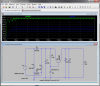
Lacking models for the 7805 and the 1N4001 I had to change the simulation a bit. I also simplified it by replacing the load by a single resistor:

I made the simulation step the breakdown voltage of the zener diode from 10V to 16V is teps of 2V (.step command). As you can see, the pre-regulator works perfectly, showing an output voltage slightly less than the zener voltage due to the base-emitter voltage drop of Q1.
V(n002) = voltage across C1.
V(n003) = voltage across R2.
This looks all good to me.
Attachments
Last edited:
Lacking models for the 7805 and the 1N4001 I had to change the simulation a bit. I also simplified it by replacing the load by a single resistor:
I made the simulation step the breakdown voltage of the zener diode from 10V to 16V is teps of 2V (.step command). As you can see, the pre-regulator works perfectly, showing an output voltage slightly less than the zener voltage due to the base-emitter voltage drop of Q1.
V(n002) = voltage across C1.
V(n003) = voltage across R2.
This looks all good to me.
Excellent Harald! Then I can order the caps and proceed, thank you
Interesting that when I took out the regulator and changed the value of the zener, the simulation performed as expected. I wonder why the regulator was showing several volts dropped? Instead of the expected zener voltages of 10,12,15 it was showing roughly 8v. I will test on breadboard when I have all the components to see.
Thanks again

I finished assembling the circuit, checked all my connections, but did not get the anticipated outcome....
I used a 5v supply to test the circuit starting at the v. regulator, negative on common pin 2 and positive 5vdc at pin 3 out. No external AC signal was available so I left that open. The Green LED comes on indicating system dry, status ok, when the input signal is injected, the Red LED comes on, green goes out. When input signal is taken away, there is a long delay before switching back. I assume this indicates the need for a resistor somewhere in the circuit to drain another part of the circuit (cap possibly).
Do I need another 1k across the cathode and positive rail like in the Green LED?
Edit:
I tried the 1k resistor for the Red LED, but it did not work.... Any ideas?
Last edited:
- Joined
- Nov 28, 2011
- Messages
- 8,393
Yes, the cap that smoothes the rectified control voltage, C3 in post #64, is much higher than it needs to be.
I must have missed this thread completely. Now, coming in with fresh eyes, I can see that the circuit doesn't need to be very complicated at all.
No regulator is needed for a simple transistor circuit like this; as long as the design and component values are chosen to ensure it will do what it should do over the widest range of input voltages, there's no problem. Steve pointed this out in post #23 but it didn't go anywhere.
With a maximum current drain of only 10 mA, there's no need to full-wave-rectify the supply either. These changes eliminate four diodes, four capacitors, a transistor, the regulator, and one resistor.
Also I have a suggestion for a better LED drive circuit. It doesn't eliminate any components but it's a clever design and I like it. So here's my suggested design:

Note that R3 and R4 must be rated for 1W dissipation; at all times, one of them will be dissipating about 0.3W. Here are the simulation waveforms:

The green trace is the AC coming in on the CTRL net. I've assumed it's a 60 Hz sinewave at 3.39V RMS. In my simulation it's generated by a separate circuit that I haven't shown.
The red and blue traces are the currents in the LEDs, which relate to the current markings on the right side. Whichever LED is illuminated will have about 8 mA flowing through it.
When the AC at CTRL disappears, there is a short time during which the illumination changes from one LED to the other. It looks like it's about 0.3 seconds. You can reduce this time if you want, by changing C2 from 1 µF to 2.2 µF and adding a 10k resistor across it.
The LED driver circuit is a clever little circuit that Steve likes to post as a MOSFET gate drive circuit. I don't know what it's called.
When AC is present on CTRL, current through D2 charges up C2 and current flows through R1 and into Q1's base, biasing it ON. It pulls its collector low (to less than 0.5V anyway) and this pulls the E2 net below 1.5V through D3. This leaves insufficient voltage across LED2 for it to light, and applies almost the full supply voltage (VCC) (about 40V) across LED1 and R3.
That part of the circuit would be enough to give a correct indication when AC is present on CTRL, but without Q2, when AC disappears from CTRL and Q1 turns OFF, its collector would not pull up fully to the positive rail. The E2 net would sit about half way between 0V and VCC, and both LEDs would light at half brightness.
So Q2 takes over in this situation. When Q1 turns OFF, its collector is pulled almost fully to VCC by R2. The LEDs don't affect this voltage because D3 is reverse biased at this time, as its cathode is being pulled up to VCC. Q2 is connected as an emitter follower, and it pulls its emitter up to about 0.7V lower than its base, which is less than 1V below the VCC rail. Only a small current flows into Q2's base, so very little voltage is dropped across R2. Since the collector-emitter voltage of Q2 is less than about 1V, there isn't enough voltage across LED1 for it to illuminate, and almost the full supply voltage appears across R4 and LED2.
D3 also protects Q2's base-emitter junction against reverse bias. If a transistor's base-emitter junction is reverse-biased by more than about 7V, this will damage the transistor. So that's another nice trick which makes this circuit clever.
I haven't shown which LED should be red and which should be green. Actually I forgot, but you should be able to work this out, now that you understand the circuit, right?
Some other comments for this thread.
We have all been assuming that your 3.39 VAC indication is fully floating, and that it's valid to connect one side of it to the 0V rail of your LED circuit. Are you sure that's true? Can you tell us some details about where this signal comes from? Back in post #8 you said it's from an irrigation controller. Can you tell us the make and model?
An AC voltage source in LTSpice is specified with the peak voltage, not the RMS voltage. This is a real trap for young players, and I personally think LTSpice should display a big reminder about this on the parameter entry field for the voltage and current sources when a sinewave is selected, because sinusoidal voltages are (by default) always specified as RMS values.
So if your transformer voltage source is 28.5V AC RMS, the peak voltage will be sqrt(2) times that value, i.e. about 40.3V, and that's the value you should enter for the voltage in LTSpice.
Harald, if you're reading this, perhaps you should add a warning about this, and a warning about using "Meg" instead of "M", to one of your LTSpice resources.
I must have missed this thread completely. Now, coming in with fresh eyes, I can see that the circuit doesn't need to be very complicated at all.
No regulator is needed for a simple transistor circuit like this; as long as the design and component values are chosen to ensure it will do what it should do over the widest range of input voltages, there's no problem. Steve pointed this out in post #23 but it didn't go anywhere.
With a maximum current drain of only 10 mA, there's no need to full-wave-rectify the supply either. These changes eliminate four diodes, four capacitors, a transistor, the regulator, and one resistor.
Also I have a suggestion for a better LED drive circuit. It doesn't eliminate any components but it's a clever design and I like it. So here's my suggested design:
Note that R3 and R4 must be rated for 1W dissipation; at all times, one of them will be dissipating about 0.3W. Here are the simulation waveforms:
The green trace is the AC coming in on the CTRL net. I've assumed it's a 60 Hz sinewave at 3.39V RMS. In my simulation it's generated by a separate circuit that I haven't shown.
The red and blue traces are the currents in the LEDs, which relate to the current markings on the right side. Whichever LED is illuminated will have about 8 mA flowing through it.
When the AC at CTRL disappears, there is a short time during which the illumination changes from one LED to the other. It looks like it's about 0.3 seconds. You can reduce this time if you want, by changing C2 from 1 µF to 2.2 µF and adding a 10k resistor across it.
The LED driver circuit is a clever little circuit that Steve likes to post as a MOSFET gate drive circuit. I don't know what it's called.
When AC is present on CTRL, current through D2 charges up C2 and current flows through R1 and into Q1's base, biasing it ON. It pulls its collector low (to less than 0.5V anyway) and this pulls the E2 net below 1.5V through D3. This leaves insufficient voltage across LED2 for it to light, and applies almost the full supply voltage (VCC) (about 40V) across LED1 and R3.
That part of the circuit would be enough to give a correct indication when AC is present on CTRL, but without Q2, when AC disappears from CTRL and Q1 turns OFF, its collector would not pull up fully to the positive rail. The E2 net would sit about half way between 0V and VCC, and both LEDs would light at half brightness.
So Q2 takes over in this situation. When Q1 turns OFF, its collector is pulled almost fully to VCC by R2. The LEDs don't affect this voltage because D3 is reverse biased at this time, as its cathode is being pulled up to VCC. Q2 is connected as an emitter follower, and it pulls its emitter up to about 0.7V lower than its base, which is less than 1V below the VCC rail. Only a small current flows into Q2's base, so very little voltage is dropped across R2. Since the collector-emitter voltage of Q2 is less than about 1V, there isn't enough voltage across LED1 for it to illuminate, and almost the full supply voltage appears across R4 and LED2.
D3 also protects Q2's base-emitter junction against reverse bias. If a transistor's base-emitter junction is reverse-biased by more than about 7V, this will damage the transistor. So that's another nice trick which makes this circuit clever.
I haven't shown which LED should be red and which should be green. Actually I forgot, but you should be able to work this out, now that you understand the circuit, right?
Some other comments for this thread.
We have all been assuming that your 3.39 VAC indication is fully floating, and that it's valid to connect one side of it to the 0V rail of your LED circuit. Are you sure that's true? Can you tell us some details about where this signal comes from? Back in post #8 you said it's from an irrigation controller. Can you tell us the make and model?
An AC voltage source in LTSpice is specified with the peak voltage, not the RMS voltage. This is a real trap for young players, and I personally think LTSpice should display a big reminder about this on the parameter entry field for the voltage and current sources when a sinewave is selected, because sinusoidal voltages are (by default) always specified as RMS values.
So if your transformer voltage source is 28.5V AC RMS, the peak voltage will be sqrt(2) times that value, i.e. about 40.3V, and that's the value you should enter for the voltage in LTSpice.
Harald, if you're reading this, perhaps you should add a warning about this, and a warning about using "Meg" instead of "M", to one of your LTSpice resources.
LOL, now you say it doesn't have to be so complicated! I just finished all those connections last night!!I must have missed this thread completely. Now, coming in with fresh eyes, I can see that the circuit doesn't need to be very complicated at all.
Steve did point this out, but I was concerned with too much variability in the supply voltage. It turns out that the supply is stable despite the solenoids being actuated. I had the parts on hand for building a regulated supply, so I figured that would be the easiest for me to do. I thought I understood it better than cap fed supplies as well.No regulator is needed for a simple transistor circuit like this; as long as the design and component values are chosen to ensure it will do what it should do over the widest range of input voltages, there's no problem. Steve pointed this out in post #33 but it didn't go anywhere.
The irrigation controller is a Hunter SRC 900i
The wall adapter is rated at 24VAC and outputs 29.2VAC.
This is a question that came to me as I was getting ready to assemble last night and I shelved it as being a dumb question!! I thought that there was no return for the AC signal, but then reasoned that since the signal is produced by the control unit and the control unit is powered by the wall adapter, then the AC signal would first power up the associated cap, then go through the resistor R6, through Q2's base and out the emitter to the ground rail which would then go back through the bridge and return on the AC neutral. Is this not correct?We have all been assuming that your 3.39 VAC indication is fully floating, and that it's valid to connect one side of it to the 0V rail of your LED circuit. Are you sure that's true? Can you tell us some details about where this signal comes from? Back in post #8 you said it's from an irrigation controller. Can you tell us the make and model?
The unit I built last night works, just doesn't change over quick enough for my taste. It really is a minor problem as the irrigation control status doesn't change that quick either. It senses if the sensor is wet or dry.
LOL C3 exploded when I connected it to the actual circuit! I am glad it was in a case when it happened! Confused as to why that happened - it was rated at 10V and the simulation showed about 2.7v across it. Was it because I used a polarized capacitor? Here's a picture of the aftermath for everyone's amusement ;-)

LOL C3 exploded when I connected it to the actual circuit! I am glad it was in a case when it happened! Confused as to why that happened - it was rated at 10V and the simulation showed about 2.7v across it. Was it because I used a polarized capacitor? Here's a picture of the aftermath for everyone's amusement ;-)
2.7V in simulation but what was the voltage in real life ?
maybe you had in the wrong way around ? ( you wouldn't do that would you ... have to ask
)D
Both good questions... and as the commercial always says: the world may never know2.7V in simulation but what was the voltage in real life ?
maybe you had in the wrong way around ? ( you wouldn't do that would you ... have to ask
D
- Joined
- Nov 28, 2011
- Messages
- 8,393
OK, thanks for the link to the irrigation controller. I guess you want to monitor the status of the Hunter Mini-Clik or Rain-Clik sensor, right?
The sensor provides a dry (pun not intended) contact, i.e. a contact that's fully isolated from everything, and the irrigation controller will test the state of that contact by applying a voltage across it through a resistance, and measuring the voltage across the resistor, or the voltage across the switch. But the irrigation controller manual does not describe the details of how it does this, and there are many ways that it could be working. Adding an external circuit, as you want to do, could cause at least two problems.
First, there will be SOME kind of connection inside the irrigation controller between its power input and the terminals that you connect the rain sensor to, and if you power that LED monitoring circuit from the "24V" AC supply that powers the irrigation controller, and connect its 0V rail to one of those terminals, you might cause damage or misbehaviour to either or both circuits.
I think it's likely that the irrigation controller bridge rectifies the input supply, and one of the rain sensor terminals may be connected to its internal 0V rail. In that case, if your circuit also bridge rectified the input supply, and you connected its 0V rail to that terminal, everything would be OK. But any other combination would cause a problem of one kind or another.
Second, the LED circuit affects the characteristics of the signal it monitors. For example, even ignoring the power supply conflict problem, if you connect a monitoring circuit across the switch, when the switch goes open circuit there will still be some current flowing into the monitoring circuit, and this could cause the irrigation controller to think that the switch is closed, depending on the particular voltage or current thresholds it uses.
The obvious solution here is to intercept the signal from the rain sensor (which is a dry contact) and use a relay to split it into two independent signals; one for the LEDs, and one for the irrigation controller. This would be done using a circuit board that connects to the irrigation controller with four wires (two for AC power to the circuit board, and two for the rain detect signal to the irrigation controller), and connects to the rain detector with two wires.

This is a great example of why it's best to provide all of the information up-front when asking for help. This thread has now had 74 posts from at least three contributors, but the proper answer could have been found within a few posts and a few days.
BTW for the relay you can use any DPDT relay with a 24V coil and at least 480Ω coil resistance. Any of these is suitable: http://www.digikey.com/product-sear...nSort=1000011&stock=1&quantity=1&pageSize=250
The sensor provides a dry (pun not intended) contact, i.e. a contact that's fully isolated from everything, and the irrigation controller will test the state of that contact by applying a voltage across it through a resistance, and measuring the voltage across the resistor, or the voltage across the switch. But the irrigation controller manual does not describe the details of how it does this, and there are many ways that it could be working. Adding an external circuit, as you want to do, could cause at least two problems.
First, there will be SOME kind of connection inside the irrigation controller between its power input and the terminals that you connect the rain sensor to, and if you power that LED monitoring circuit from the "24V" AC supply that powers the irrigation controller, and connect its 0V rail to one of those terminals, you might cause damage or misbehaviour to either or both circuits.
I think it's likely that the irrigation controller bridge rectifies the input supply, and one of the rain sensor terminals may be connected to its internal 0V rail. In that case, if your circuit also bridge rectified the input supply, and you connected its 0V rail to that terminal, everything would be OK. But any other combination would cause a problem of one kind or another.
Second, the LED circuit affects the characteristics of the signal it monitors. For example, even ignoring the power supply conflict problem, if you connect a monitoring circuit across the switch, when the switch goes open circuit there will still be some current flowing into the monitoring circuit, and this could cause the irrigation controller to think that the switch is closed, depending on the particular voltage or current thresholds it uses.
The obvious solution here is to intercept the signal from the rain sensor (which is a dry contact) and use a relay to split it into two independent signals; one for the LEDs, and one for the irrigation controller. This would be done using a circuit board that connects to the irrigation controller with four wires (two for AC power to the circuit board, and two for the rain detect signal to the irrigation controller), and connects to the rain detector with two wires.
This is a great example of why it's best to provide all of the information up-front when asking for help. This thread has now had 74 posts from at least three contributors, but the proper answer could have been found within a few posts and a few days.
BTW for the relay you can use any DPDT relay with a 24V coil and at least 480Ω coil resistance. Any of these is suitable: http://www.digikey.com/product-sear...nSort=1000011&stock=1&quantity=1&pageSize=250
Correct, Rain-Clik.OK, thanks for the link to the irrigation controller. I guess you want to monitor the status of the Hunter Mini-Clik or Rain-Clik sensor, right?
The sensor provides a dry (pun not intended) contact, i.e. a contact that's fully isolated from everything, and the irrigation controller will test the state of that contact by applying a voltage across it through a resistance, and measuring the voltage across the resistor, or the voltage across the switch. But the irrigation controller manual does not describe the details of how it does this, and there are many ways that it could be working. Adding an external circuit, as you want to do, could cause at least two problems.
Good points made above and in subsequent paragraphs. I didn't realize that when I thought of this circuit and honestly at only a scant 8mA I thought there wouldn't be much conflict. With the switch installed and wet, the AC signal is 3.48V (was 3.39V).
As for internals, I can only tell you that the irrigation controller has a row of terminal blocks with screws, 24 VAC in from the adapter goes under one pair, the rain sensor goes under a separate pair named RS and C. The common terminal also has the common of the solenoids terminated under it.
Ah, but that is not anyone else's fault. I had a preconceived notion of what I wanted to do based on some newly acquired knowledge. And we all know what happens with knowledge but no experience, rightThis is a great example of why it's best to provide all of the information up-front when asking for help. This thread has now had 74 posts from at least three contributors, but the proper answer could have been found within a few posts and a few days.
I should also mention I was trying to reuse the old wireless receiver case that the original wireless rain-clik had come in. I was able to gut it and install a small board with all the parts. I thought it was uber cool to hack the old parts
I still have the old board and there is small relay on it - 24v JS1-24V-F AJS1312F- Joined
- Nov 28, 2011
- Messages
- 8,393
Right, well that fits with my suggestion - the "C" pin would probably be the circuitry's 0V rail. But in that case I would expect to see DC voltage on the "RS" pin when the rain sensor switch is open, not AC voltage.As for internals, I can only tell you that the irrigation controller has a row of terminal blocks with screws, 24 VAC in from the adapter goes under one pair, the rain sensor goes under a separate pair named RS and C. The common terminal also has the common of the solenoids terminated under it.
But the point is we don't really know, so now we know the full story, the best way to handle it is the circuit I showed.
I didn't say it was! Often, we do ask for clarification and full details, but if you seem quite clear in your requirements, sometimes we just accept them and work from that basis. This is a really good example of why that can be a bad idea.Ah, but that is not anyone else's fault.
Yeah. I see this all the time. People tell us exactly how they want to do something, without going back to the basics and describing the overall project. Often they have made assumptions, or restricted their options, because of their limited experience. We get into a game of follow-the-leader with a blind person!I had a preconceived notion of what I wanted to do based on some newly acquired knowledge. And we all know what happens with knowledge but no experience, right
Don't feel any need to apologise to me though. I didn't even hear about this thread until yesterday!
That looks like a SPNC relay. No use for this project :-(I should also mention I was trying to reuse the old wireless receiver case that the original wireless rain-clik had come in. I was able to gut it and install a small board with all the parts. I thought it was uber cool to hack the old parts
Right, well that fits with my suggestion - the "C" pin would probably be the circuitry's 0V rail. But in that case I would expect to see DC voltage on the "RS" pin when the rain sensor switch is open, not AC voltage.
But the point is we don't really know, so now we know the full story, the best way to handle it is the circuit I showed.
I didn't say it was! Often, we do ask for clarification and full details, but if you seem quite clear in your requirements, sometimes we just accept them and work from that basis. This is a really good example of why that can be a bad idea.
Yeah. I see this all the time. People tell us exactly how they want to do something, without going back to the basics and describing the overall project. Often they have made assumptions, or restricted their options, because of their limited experience. We get into a game of follow-the-leader with a blind person!
Don't feel any need to apologise to me though. I didn't even hear about this thread until yesterday!
That looks like a SPNC relay. No use for this project :-(
LOL, no but I was responsible for the direction this took, so I indeed am responsible for the poor outcome. My apologies. I did have fun, a sore neck from soldering all those connections - I did it point to point with a poorly thought out board arrangement and a blown cap!
As you said above, the C terminal is common, but then you say DC is what you expected? When I used my DMM on those terminals I got AC voltage when the switch was opened.
The more I look at the schematic the more I think its pure genius, simple and efficient... Bravo! I would have never of thought of substituting the contacts leads for the rain sensor's contacts. I kinda thought that sensor was more than just a switch.
- Joined
- Nov 28, 2011
- Messages
- 8,393
And no DC voltage? What are the specifications for the control valves? Are they AC or DC?As you said above, the C terminal is common, but then you say DC is what you expected? When I used my DMM on those terminals I got AC voltage when the switch was opened.
Not according to the data sheet. Just a switch contact.The more I look at the schematic the more I think its pure genius, simple and efficient... Bravo! I would have never of thought of substituting the contacts leads for the rain sensor's contacts. I kinda thought that sensor was more than just a switch.
And no DC voltage? What are the specifications for the control valves? Are they AC or DC?
Not according to the data sheet. Just a switch contact.
Definitely AC - the last page of that link shows the max output including a master solenoid as AC. Also this page shows troubleshooting the valves using AC on DMM
http://www.hunterindustries.com/support/valves-testing-voltage-controller-and-solenoid
Cool, just a switch, makes that change quite logical.
Would it matter if AC is on one 1/2 of the relay with DC on the other?
- Joined
- Nov 28, 2011
- Messages
- 8,393
OK, the valves and the circuit that detects the state of the rain sensor switch are presumably connected directly to the 24V AC power source. Outputs (to the solenoid valves) are via relays, and the input (from the rain sensor) is probably via an optocoupler. All my comments in post #74 apply.
If you had used a bridge rectifier in your external circuit, and connected its 0V rail to the "C" pin, you would have shorted out the AC adapter. If you had used my design in post #68 and you happened to connect it the right way round to the 24VAC inputs, it might have worked. But using a relay removes all the guesswork.
If you had used a bridge rectifier in your external circuit, and connected its 0V rail to the "C" pin, you would have shorted out the AC adapter. If you had used my design in post #68 and you happened to connect it the right way round to the 24VAC inputs, it might have worked. But using a relay removes all the guesswork.
Similar threads
- Replies
- 10
- Views
- 3K
- Replies
- 0
- Views
- 2K
- Replies
- 3
- Views
- 2K