Relay LED Optocoupler Circuit

fshgtai

May 12, 2024
4
Joined
May 12, 2024
Messages
4
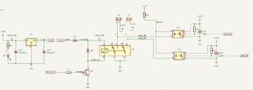
Hi, I am working on a design that uses a relay to control LED lights. The schematic shows +12VDC LEDs connected to the (+) terminals, while the other end (-) of the terminal is connected to both an opto-coupler and the relay, which then feeds into the MCU. Regardless of whether the relay is on or off, I only see a high signal at the opto-coupler output. I'm not sure what the issue is with the attached circuit. Can anyone help me identify and rectify the problem? I have already designed a PCB with this circuit and would like to avoid repeating the same mistake in the new build. Thank you
 

Attachments

  • Screenshot 2024-05-12 153644.jpg
    Screenshot 2024-05-12 153644.jpg
    60.6 KB · Views: 11

Bluejets

Oct 5, 2014
7,374
Joined
Oct 5, 2014
Messages
7,374
Show the rest of the circuit for the LEDs.
The opto is open collector.
What are the LED specs?
 

Bluejets

Oct 5, 2014
7,374
Joined
Oct 5, 2014
Messages
7,374
The remaining part is the input to the MCU only.
Don't follow your logic ........ as I said, the opto output is open collector.
I only see a high signal at the opto-coupler output
What is the "high" level in terms of voltage?
What happens if you disconnect R13?
What type number is the opto?
You might be getting yourself all bamboozeled by the type of opto you are using.(Base opto diode)
 
Last edited:

fshgtai

May 12, 2024
4
Joined
May 12, 2024
Messages
4

Harald Kapp

Moderator
Moderator
Nov 17, 2011
14,271
Joined
Nov 17, 2011
Messages
14,271
The optocoupler you're using is a high speed type - overkill for this application.
Anyway, the optocoupler is specified for an LED current of 16 mA. Your current limiting resistor is 2.2 k. With a forward voltage of the LEd of 1.6 V, that makes for [imath]I_{LED} = \frac{12 V - 1.6 V}{2.2 k\Omega} = 4.7 mA[/imath], shared by both LEDs, so each LED is driven by ~ 2.4 mA. This is way to low for this optocoupler's specs.
Apart from that, paralleling LEDs as in your circuit is not a good design. The LED current will be split asymmetrically as the forward voltages of both LEDs are never the same. Therefore my recommendations:
  1. Use separate current limiting resistors for each LED.
  2. Use 681 Ohm resistors (E48 standard value) to drive ~ 16 mA per LED.

Question: Why do you use 2 separate feedback optocouplers? The relay is a DPDT type. So whenever one contact is active, the other contact will be active, too. Both optocouplers will always deliver teh same output. Imho s single optocoupler is sufficient.
 

fshgtai

May 12, 2024
4
Joined
May 12, 2024
Messages
4
The optocoupler you're using is a high speed type - overkill for this application.
Anyway, the optocoupler is specified for an LED current of 16 mA. Your current limiting resistor is 2.2 k. With a forward voltage of the LEd of 1.6 V, that makes for [imath]I_{LED} = \frac{12 V - 1.6 V}{2.2 k\Omega} = 4.7 mA[/imath], shared by both LEDs, so each LED is driven by ~ 2.4 mA. This is way to low for this optocoupler's specs.
Apart from that, paralleling LEDs as in your circuit is not a good design. The LED current will be split asymmetrically as the forward voltages of both LEDs are never the same. Therefore my recommendations:
  1. Use separate current limiting resistors for each LED.
  2. Use 681 Ohm resistors (E48 standard value) to drive ~ 16 mA per LED.

Question: Why do you use 2 separate feedback optocouplers? The relay is a DPDT type. So whenever one contact is active, the other contact will be active, too. Both optocouplers will always deliver teh same output. Imho s single optocoupler is sufficient.
Thank you for your response. You were right; changing the resistor to 680 ohms made the circuit work. Regarding your question, I implemented this circuit for an initial test to see if, should one input fail, I could switch to a second input, which I did. I disconnected the resistor trace from one opto-coupler and changed the resistor as well. Now, at least one feedback is working, which is good enough for now.
 

bidrohini

Feb 1, 2023
213
Joined
Feb 1, 2023
Messages
213
Disconnect the MCU and test the opto-coupler output behavior independently.
 

AnalogKid

Jun 10, 2015
3,045
Joined
Jun 10, 2015
Messages
3,045
Both sides of the opto couplers are referenced to the same GND. Because of this, the optos can be replaced with simple 2-resistor voltage dividers.

ak
 
Top