Resistor issue

wounder

Jun 15, 2019
13
Joined
Jun 15, 2019
Messages
13
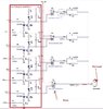
The given circuit is the fan speed control.
the input 230v is divide with different capacitor , resistor arrangement.
why my R22 resistor(4.7 ohm,1 watt) damaged when RL4 relay is active?
Other resistor has not yet any damage issue .
I was changed the wattage rating (4.7 ohm,2 watt)but still damaged the resistor.
I am used a table fan motor(35 watt,2650 rpm).
Instead when using ceiling fan ,resistor damage issue not seen yet .
Why this happens?
Any solution could you suggest?
note:
when i remove the resistor and short the terminal ,then measure using multi meter at output seems voltage is high enough.
 

Attachments

  • circuit.jpg
    circuit.jpg
    98.8 KB · Views: 9
Last edited:

wounder

Jun 15, 2019
13
Joined
Jun 15, 2019
Messages
13
You do realise that small induction motors like fan motors can be speed controlled simply by switching a capacitor in series.
As an example, 60w ceiling fans use between 1,5uF and 2.5uF as a 3 speed control ( hi speed direct)
Most are 2 caps in the one casing as per link below.

https://www.ebay.com.au/itm/Black-C...931691?hash=item214570a7eb:g:TdgAAOSwSP9batHf


View attachment 45526
ok..fine
but why resistor in circuit [mentioned] is damaged ?
any solution for overcoming issue?
 

73's de Edd

Aug 21, 2015
3,730
Joined
Aug 21, 2015
Messages
3,730
Sir wounder . . . . .

Git out yer BIG ENGLISH to ? Dictionary . . . . with ALL appendices.

I am looking at your first messages on another posting of yours.
Sooooooooooo . . . . . now . . . for some questions and explanations .
You have three of the SAME parts being used, with R19 and R23 as being the same as your NOW problematic R22.
Now you have gone and put a common 4.7 ohm 1 thru 2 watt resistor in R22 position. . . . .GETS HOT.!
PLUS, for that speed, you are using the RL4 relay position and the associated 4.7 ufd series capacitor, which consumes the most power of the three speeds.

Normal operation is for the power that is applied thru the 3-4 relay contacts to then pass thru that R22 " resistor " *****, which in reality is a surge absorption thermistor which is absorbing the increased initial start up power, as being required from having an immobile / stopped motor rotor.

After initial starting rotation the power requirement rapidly drops as the motor speeds up. The power passage thru the R22 also declines proportionally.
UNLESS you have a common film or wirewound resistor NOW being used for R22.

In the case of the surge absorption thermistor being used here, it is only ~4.7 ohms when COLD and its resistance will decline with power passing thru it.
With it starting at 4.7 ohms, after ~15 seconds of running time and its slightly warming up the resistance typically will then have plummet on down to ~ 1/2 ohm.
Therefore, THEN there is very little power loss in the unit, and with it then only being very slightly warm.

With your STANDARD resistor being used and it forever STAYING at 4.7 ohms that is more power being continually demanded thru it, than it can tolerate .

Soooooooooooo if you have replaced ONLY that R22 and the other units are being the fans original (and proper) units, that is what is happening to you .

*****
On the schematic . . . . Read that part . . . . . it shows . . . .4E7 / 1W, TH . . . . . . . .with TH as in it being a THERMISTOR (with it having a Neg Temp Coeff)

NOW where are you located . . . and how possible, is a supplier for that correct part being available ?


73's de Edd . . . . .


The hardest thing in life to learn, is exactly which bridge to cross . . . . . and which to burn.

 
Last edited:

hevans1944

Hop - AC8NS
Jun 21, 2012
4,968
Joined
Jun 21, 2012
Messages
4,968
The hardest thing in life to learn, is exactly which bridge to cross . . . . . and which to burn.
So, the OP has gone from burning contacts to burning resistors, eh? Nice catch, Edd, noticing the "resistor" is actually a negative-temperature-coefficient thermistor. Haven't seen those is quite awhile! Perhaps this is a bridge better burned than crossed.

From now on (stick tongue firmly in cheek), maybe this forum should require well-composed, in-focus, pictures of suspect components before we begin a lengthy dialog. This could be especially helpful for those posting here that do not speak, read, or write English as their native language... a picture can be worth bunches and bunches of words in that case.

And even if your English vocabulary, grammar, spelling, and composition are all excellent, a few good pictures are always appreciated. Try limiting the resolution of each picture to 1024 x 768 pixels to make sure the image uploads successfully. I don't know if that is an upper limit on size, but I do know that it worked for me on at least one image I tried to upload here.
 
Top