If the secondary of your step-down power transformer were center-tapped, you could (1) remove the "ground" where D2 and D3 are connected, (2) connect the center-tap of the transformer secondary to "ground", and (3) get a negative output voltage where D2 and D3 are connected together, and (4) get a positive output voltage where D1 and D4 are connected together.
This is a full-wave rectifying bridge circuit, whether the center-tap is grounded or absent. At any given half-cycle of the AC line voltage, two of the diodes will be forward biased and two will be reverse biased. If all you need is a single polarity of output, and a center-tapped secondary is available, diodes D2 and D3 can be eliminated and the center-tap becomes "ground" with a positive output voltage from the common connection between D1 and D4 and "ground". On the other hand, if you DON'T have a center-tapped transformer, diodes D2 and D3 allow you to have a positive output at twice the voltage that the center-tapped circuit provides.
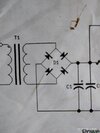
For the circuit you have shown, with polarity markings on opposite ends of the windings, imagine that these markings represent the polarity of one half-cycle of the AC waveform. A half-cycle later, these polarities will be reversed, so let's treat that as a separate incident.
In the first case, when the top of the secondary winding is positive with respect to the bottom of the winding, diodes D1 and D2 will be forward biased through load resistor R
L. A half-cycle later the top of the secondary winding is negative with respect to the bottom of the winding. In other words the + and - signs on your schematic reverse. This causes diodes D4 and D3 to become forward biased, again the circuit is from the bottom of the winding, through D4, then through the resistive load to "ground," and finally through D3 to the other terminal of the winding.
Note that "ground" in your circuit serves no purpose at all, except to act as a common point of reference for measuring the voltage drop across R
L. If you remove the connection to "ground" at D2 and D3, and ground the center-tap of the secondary, you will have a bi-polar output power supply: positive output where D1 and D4 are connected together, and negative output where D2 and D3 are connected together. It will still need filtering because of the 120 Hz full-wave rectified sine waveform.
And it is online as a center tap rectifier.
Please provide a working link to where this circuit is described as a "center tap rectifier" because it clearly is not.

")