Sherwood RD-6500 A/V receiver blowing fuses

diode

Jan 25, 2016
31
Joined
Jan 25, 2016
Messages
31
Hello, I have this Sherwood receiver and bought it not powering on. When powered up the red light comes on but nothing else. So I took the cover off and noticed the 6a fuse was blown on the power board. So I put another fuse in it and it popped. Then I bought some fuses, disconnected the big transformer from the power board and the main boards. Then turning on the receiver the fuse did not blow, so I plugged the trans. back into everything but the main board where there are 3 12 gauge wires going into it. Then turning on the receiver, I now have the display working and the fuse holds.

I broke out a voltmeter and was trying to test what voltage is coming out of the 3 wire connector that I am leaving unplugged and the testing has been inconclusive. Nothing on the receiver seems burnt as I cannot smell anything. I am looking for some advice on where to look next. I am assuming the transformer is good but am not sure what kind of voltage should be coming out of it. There are a couple big diodes on the main board I want to test next. Any input would be much appreciated. I have an oscilloscope but don't know how to use it.

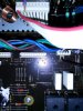
The heatsinks in the picture attached to what I believe are transistors are warm since the receiver has been on. The empty connector is where I disconnected the transformer so it wouldn't blow fuses.
 

Attachments

  • sherwood.jpg
    sherwood.jpg
    49.2 KB · Views: 665

shrtrnd

Jan 15, 2010
3,901
Joined
Jan 15, 2010
Messages
3,901
It's highly unusual for a transformer itself to go bad. You've probably got a short circuit somewhere in the power supply circuit.
We get this question a lot and most people agree that the first thing to check are the big electrolytic capacitors, because they go bad first.
That's not to discount the possibility of something else, it's just the first thing to check.
Since you blow fuses, you can pretty much count on it being a shorted component. Diode or transistor (the larger power transistors usually).
If you're waiting for something specific to check, I'd start with MAKING SURE THE POWER CORD IS DISCONNECTED FROM THE WALL SOCKET,
And then take ohmmeter readings across the terminals of the big power transistors. You're looking for a direct short across the terminals of any one of those transistors.
The first bit of advice you're going to get, is to Google on-line for a schematic of your receiver. A lot of places charge, but you may be able to find a free copy on-line.
Schematics for your model are the golden fleece of troubleshooting. They tell you what's in the circuit and where to look to trace the problem.
Find a schematic for the make and model of your receiver, take a quick check of those power transistors for shorts, and tell us what you've got.
Plenty of people here will be glad to direct you.
 

diode

Jan 25, 2016
31
Joined
Jan 25, 2016
Messages
31
What are the square objects with the + - and ~ signs on it?
 

shrtrnd

Jan 15, 2010
3,901
Joined
Jan 15, 2010
Messages
3,901
Bridge rectifiers. Essentially four diodes in a bridge configuration, encapsulated in one package.
There are four leads from the device into the circuit board. If you check the sides of the device, you'll probably find a part number on one of the sides.
 

73's de Edd

Aug 21, 2015
3,730
Joined
Aug 21, 2015
Messages
3,730
.


Sir diode . . . . . .

Rejoice . . . . your answers are on the way.

Herewith, one mark up on the initial relevant locations on the top of that units mainboard.

When you pulled the 3 pin connector (You can see it now as GREEN CP101) you removed the main POWER AC voltage from the units transformer to the MAIN POWER supply of the unit.
This supply feeds the REALLY POWER hungry portion of the receiver . . .the audio output section.
The rest of the set is receiving its power from smaller sub- power supplys.

Sequenced Power Supply and Loads Troubleshooting :

This is to be done with no AC power applied . . . just relying on an ohmming out of areas.

Initially reinstall your CP101 plug that you removed earlier.

Take ohmmeter in hand, set to lowest ohms scale and move to connector BLUE CP111.
Note the BLACK arrow and the ground connection, that it is pointing out.
Place one meter probe on that connection and the other probe on the other ground connection next to it.
Take note of your instruments reading and its display on the reading of a dead short.
Move one probe on over to the GREY arrow and take note of the metered reading, and then shift to the RED arrow and take its reading.
I am expecting one of the two to be reading much lower ohmmage than the other, and if really bad, that reading will be down very low, towards the very initial test , by the simulating of a totally shorted condition.

If finding one B+ or B- supply to be at fault, the connector which mates with CP111 needs to be unplugged and that will let you individually ohm out the B+and B- to ground pins, as referenced too ground.
Repeat at the CP111 in the main PCB and see if the condition still exists, if so the main suspect is one of the YELLOWE BD101 or BD102 rectifiers, with a crunched internal diode(s).
Least likely would be the associated C179 and C180 main raw DC filters.

The other possibility is for the AUDIO POWER OUTPUT stage, being the area of the unit having the overload fault, which was connected to the power supply by that connector that you now have unplugged.
Take that connector and ohm out for imbalanced resistance between ground and the B+ B- pins.

By now your reading should tell if the problem is on the board or over at the units audio power out stage .

Standing by for feedback of results.

TECHNICAL REFERENCING . . . .via . . . . . Board Layout: (Click on up to full size)

czrPwGi.png


Raw DC Power Supplies view:


sherwood-jpg.24662


73's de Edd

.
 

diode

Jan 25, 2016
31
Joined
Jan 25, 2016
Messages
31
My circuit doesn't look quite the same but I ohmed out 3 b+ connections at the board and 3 b- connections. All of the B+ connections were pretty much shorted to ground. Here is a picture of the b+ connections that are shorted to ground. That was testing with the connector at the b+ pins disconnected. Is that the right connector to check?
 

Attachments

  • board.jpg
    board.jpg
    246.7 KB · Views: 161

73's de Edd

Aug 21, 2015
3,730
Joined
Aug 21, 2015
Messages
3,730
.

Sir diode . . . . .

Thanks for the good quality supplemental photo.

I can now differentiate between the male and female assignments of CP101 and its mate CN101.

So, it looks like they decided to up the power level carrying capacity between the power supply plug and the connection at the
power amp portion by tripling the wire count.

Now if you had the two unplugged from each other and the shorts were on the male pins of connector mounted on the main chassis,
head for the YELLOW FWB units I have marked up.
Unplug the initial connection that you unplugged to take the power transformer windings out of circuit and then, you really need to
completely pull one unit, as they are both wired in parallel . . . .not one for each of the + and - supplys, as one might think.

Do a diode test from an ~ (AC) symbol to the + and then the - to see if those two diodes are OK and then move to the other
~ (AC) symbol and test that section in the same manner.
Then you can check the one that you took out of circuit.
Now, if you lucked out . . . . . then all you have to do is contact "The mouse house" for two of these:

http://www.mouser.com/ProductDetail...V2i03Pvz7eqe1Ky2Iu7OnRpusVVJBpbX3QIJLK4wByg==

BUT . . .the hunt is not over yet, since there is a possibility of damage down the power supply stream at the audio power amp section.
So you take the female connector that goes to the audio power amp section and test it from its grounds to the + and - supply lines
just as you did on its male connector on the main PCB.

I'm hoping that no damage had been inflicted upon that section.

Whenever ? the power supply is cleaned up and operational again, never put in a line fuse and test the unit immediately.
Instead get an incandescent bulb, lamped table lamp or drop light and turn it on and test operation when using a 100 watt lamp.
Then connect two test jumper leads across its plugs blades and connect the other test clip leads ends across the now vacant AC line fuse receptacle.
We now have a lamp in line, and if you turn on the power and it is BRIGHT, we still have over loading problems.
If you turn on and the lamp slightly lights during power electrolytic charge up/surge time and then declines in brightness.
That is what is expected, since the lamp will then not pass enough power thru the line.
Only then . . . . . . might you attempt a test with line fuse in place.

Thassssit . . . . . . . . . . unless trouble is found in the power supply line to the Audio Power Amp section, with that section having a
load down problem.


73's de Edd


.
 

diode

Jan 25, 2016
31
Joined
Jan 25, 2016
Messages
31
Thanks, I will run those tests later and then report back when I figure out if the bridges are faulty. It might not be for several days as I have little time but I will surely report back. In the meantime is will make a test light.
 

diode

Jan 25, 2016
31
Joined
Jan 25, 2016
Messages
31
OK, I took the time to remove the board and take the rectifiers out. One of them has a short between the + and ~ both ways. So I will order the parts and hopefully be able to put them in by next week.
 

diode

Jan 25, 2016
31
Joined
Jan 25, 2016
Messages
31
BUT . . .the hunt is not over yet, since there is a possibility of damage down the power supply stream at the audio power amp section.
So you take the female connector that goes to the audio power amp section and test it from its grounds to the + and - supply lines
just as you did on its male connector on the main PCB.

Where exactly do I test for this and can I test it while everything is apart?
 
Top