Signal generator to drive Ultrasonic transducer

Nanobubbles

Jul 24, 2025
6
Joined
Jul 24, 2025
Messages
6
Hello Maker Pro Forum,

I'm trying to set up an ultrasonic transducer to create nanobubbles in a metal container. The first part I'm troubleshooting is trying to make sure the output is strong enough to run the ultrasonic transducer. The Ultrasonic Transducer is the BQLZR Ultrasonic Piezoelectric Transducer Speaker 28khz 100W from amazon. I have it mounted underneath my metal container. My goal is to put out a 20-25 khz 15-20 watt sin signal to drive the transducer.

The Signal generator I'm using is the
Koolertron Upgraded 15MHz DDS Signal Generator Counter,High Precision Dual-Channel Arbitrary Waveform Function Generator Frequency Meter 200MSa/s (15MHz). The maximum output, in terms of wattage, is 1 watt at 20 volts.

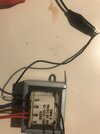
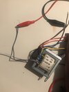
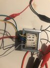
Then using a BNC to alligator clips connector, I use a
Bogen Transformer Model T725-10 10W to step up the signal. I hope I have the wiring with this transformer correct. I have it connected to the COM wire and then because I can't tell which one is the 8th tap, I have it connected to 7th wire away from the Com wire.

Then from this transformer, using alligator to banana plugs, I amplify the signal with a
Hewlett Packard 465A Laboratory Amplifier. The signal is amplified by 80DB.

Finally from the amplifier to the transducer I use banana to alligator clips to run the transducer.

I have tested my set up and all I get is a high pitched sound and no movement of water in the tub. I have a video attached to this post for people to look at it to get an idea of what I mean. My question is whether I am doing this correctly and if not, where in my set up am I going wrong?


Here is a video of my setup running. Note that although it says 10 khz instead of 20-25 khz as I said above, it still makes the same sound if outputting 10khz or 20-25 khz:

Attached are photos of my step up transformer and wiring.

Hope I have explained it clearly, appreciate any help.
 

Attachments

  • Bogen Transformer.jpg
    Bogen Transformer.jpg
    163.3 KB · Views: 3
  • Bogen Transformer 1.jpg
    Bogen Transformer 1.jpg
    169.7 KB · Views: 3
  • Bogen Transformer 2.jpg
    Bogen Transformer 2.jpg
    181.2 KB · Views: 3

Harald Kapp

Moderator
Moderator
Nov 17, 2011
14,281
Joined
Nov 17, 2011
Messages
14,281
https://www.amazon.de/-/en/Frequency-Amplifier-20Hz-100KHz-Sensitive-Precise/dp/B0CFV32WHHThe transformer you use looks like a mains transformer, suitable for 50 Hz or 60 Hz. By no means will it work as expected at 10 Khz or more.
The signal is amplified by 80DB.
The manual states that the HP465A amplifier can amplify by 20 dB or 40 dB, not 80 dB. It will also output max. 1/2 W, way less than the 15 W - 20 W you expect.
1753423655576.png
  1. get rid of the transformer.
  2. use a power amplifier suitable for 15 W - 20 W at 10 kHz - 25 kHz. Here's an example.
  3. use an inexpensive generator instead of the comparatively expensive Koolertron DDS generator. Here's an example for 8 €, here's another one, looking slightly more "professional" for 21 €.
 

Nanobubbles

Jul 24, 2025
6
Joined
Jul 24, 2025
Messages
6
Appreciate the response. That's the first and last time I'll consult Chat GPT on this project. It recommended me that amplifier and transformer. Hopefully I can sell the both of them to someone in my local area that needs them.

Just to clarify, I don't need a pre-amplifier if I use the recommended amplifier?

Is the recommendation to use a cheaper signal generator rather than the Koolertron due to how effective the cheaper signal generator works with your recommended amplifier or because the Koolertron is likely to be damaged during this experiment? Could I just use the Koolertron with your recommended amplifier?
 

Harald Kapp

Moderator
Moderator
Nov 17, 2011
14,281
Joined
Nov 17, 2011
Messages
14,281
Just to clarify, I don't need a pre-amplifier if I use the recommended amplifier?
Should not be required.
Is the recommendation to use a cheaper signal generator rather than the Koolertron due to how effective the cheaper signal generator works with your recommended amplifier or because the Koolertron is likely to be damaged during this experiment?
For driving the ultrasonic transducers in this application you don't need a high quality, low noise, low distortion signal. You can use the Koolertron, it should work with an amplifier as I showed as an example. Damage will, if at all, happen to the amplifier. The Koolertron is unlikely to be damaged - provided your setup is correct (no short circuits, proper grounding etc.). If you happen to have the Koolertron, there's no need to buy another generator. But if you need to buy one, you can save a lot of money by using a much less expensice generator.
 

poor mystic

Apr 8, 2011
1,106
Joined
Apr 8, 2011
Messages
1,106
Hi :)
I'm not sure why you need a sin signal. This is a capacitive device which you can pour charge into, and pour it back out. It seems to me that it would be easier to drive this device with a square wave.
Why not use a totem pole and just drive it plus and minus as hard as you can? 1753873466506.png
 

hevans1944

Hop - AC8NS
Jun 21, 2012
4,978
Joined
Jun 21, 2012
Messages
4,978
You should also consider the acoustic coupling between your "loudspeaker" at ultrasonic frequencies and the liquid in which you are trying to create bubbles. It sounds to me (no pun intended) that you are generating ultrasound in air and trying to couple that energy through a metal container's wall into the liquid. Is that correct? Or does the ultrasonic transducer bolt in intimate contact to the wall of the liquid's container? Also, why re-invent this wheel? Ultrasonic cleaning baths are readily available. Last time I looked at the small one we use to clean my wife's diamond rings it created lots of bubbles. Feels "funny" when I stick my fingers in the water with the machine turned on, but it does a pretty good job of removing dirt from under my fingernails. What are you going to use your "bubble maker" for?
 

Nanobubbles

Jul 24, 2025
6
Joined
Jul 24, 2025
Messages
6
@Harald Kapp Thank you, appreciate your response. I've ordered the OPA541 Low Frequency Power Amplifier Module 5A 10‑40V and will be using it with the Koolertron. I'm still looking for a power supply to use with the module and haven't found one yet.

@poor mystic I had the signal generator not being used for anything so I decided to purpose it for this project. It is capable of outputting a square wave instead of a sin wave.

@hevans1944 The ultrasonic transducer is intimately connected to the wall of the liquid container which has water in it. The original reason why I'm doing this rather than buying an ultrasonic cleaner is that most of them are fairly expensive at over $100. I figured I could make my own for cheaper since I had a signal generator lying around, not being used. I might of bit off more than I can chew perhaps. I'm open to buying an ultrasonic cleaner so long as it can do 22-25khz at 15-20 watts at least. Ultimatley I want to be able to produce these bubbles for a number of applications including but not limited to cleaning water, creating nitrate fertilizer, and even desalination.
 

73's de Edd

Aug 21, 2015
3,730
Joined
Aug 21, 2015
Messages
3,730
Using that I-E core based BOGEN transformer in " coupling " ultrasonic frequencies . . . . . . . .are you out of your rabbit ass mind ?
 

hevans1944

Hop - AC8NS
Jun 21, 2012
4,978
Joined
Jun 21, 2012
Messages
4,978
Using that I-E core based BOGEN transformer in " coupling " ultrasonic frequencies . . . . . . . .are you out of your rabbit ass mind ?
I think what @73's de Edd means is the silicon-steel I-E core of the Bogen brand transformer is not suitable for the kilohertz frequencies that you need. Perhaps you should invest in an inexpensive digital storage oscilloscope (simple single-board kits are available for around $20 if you want to get your feet wet first) to see what kind of signal is available at the transducer.

I haven't done any work lately with ultrasonics, but you might want to investigate toroid transformers made with ceramic ferrites. There might even be some folks left on this forum who can help you select an appropriate core material. Hams (amateur radio operators) wind baluns and ununs using toroid cores, so they should work for ultrasonic frequencies too with the right "mix" of core materials. Main thing seems to be avoiding saturation of the magnetic material by a judicious choice of windings and the manner in which the primary winding is driven, if the core material is otherwise suitable.

Good luck with your project. It does appear that you know what you are doing, at least in principle. As for commercial units: they do seem to be a bit overpriced considering how simple they are. I hope you are successful in making a DIY version... but, tell me, how does an ultrasonic bath help to de-salinate water?

I was under the impression that reverse osmosis filtering was the preferred method. Just add a pump, a filter, and lots of energy and... voila! Drinking water! Make enough of it and it becomes water for irrigation. With solar energy, you could turn Middle East deserts into green fields if they have nearby access to sea water, which most of them do. Pipes to carry potable water are also a well-established technology, even if you don't live near the sea. I see a bright future for desalinization plants powered with nuclear, solar, oil, natural gas, or coal energy (in that order of priority).

What are your plans if you get your DIY ultrasonic generator working?
 

Nanobubbles

Jul 24, 2025
6
Joined
Jul 24, 2025
Messages
6
I think what @73's de Edd means is the silicon-steel I-E core of the Bogen brand transformer is not suitable for the kilohertz frequencies that you need. Perhaps you should invest in an inexpensive digital storage oscilloscope (simple single-board kits are available for around $20 if you want to get your feet wet first) to see what kind of signal is available at the transducer.

I haven't done any work lately with ultrasonics, but you might want to investigate toroid transformers made with ceramic ferrites. There might even be some folks left on this forum who can help you select an appropriate core material. Hams (amateur radio operators) wind baluns and ununs using toroid cores, so they should work for ultrasonic frequencies too with the right "mix" of core materials. Main thing seems to be avoiding saturation of the magnetic material by a judicious choice of windings and the manner in which the primary winding is driven, if the core material is otherwise suitable.

Good luck with your project. It does appear that you know what you are doing, at least in principle. As for commercial units: they do seem to be a bit overpriced considering how simple they are. I hope you are successful in making a DIY version... but, tell me, how does an ultrasonic bath help to de-salinate water?

I was under the impression that reverse osmosis filtering was the preferred method. Just add a pump, a filter, and lots of energy and... voila! Drinking water! Make enough of it and it becomes water for irrigation. With solar energy, you could turn Middle East deserts into green fields if they have nearby access to sea water, which most of them do. Pipes to carry potable water are also a well-established technology, even if you don't live near the sea. I see a bright future for desalinization plants powered with nuclear, solar, oil, natural gas, or coal energy (in that order of priority).

What are your plans if you get your DIY ultrasonic generator working?

Reverse osmosis for desalination is a great method for creating fresh water from sea water and the most commercially viable at the moment.

What makes Nanobubbles interesting in relation to desalination is they act like nanoparticles that have different properties, especially if you change up the gas, having to do with the interfacial boundary between it and other dissolved ions. 10.1016/j.tsep.2024.102590. This paper talks about how nanobubbles can have a double layer that attracts negative and positive ions on top of each other.

Also here's a paper where they use air-nanobubbles to clean reverse osmosis filters, removing the salt build up off of them without the usage of harsh chemicals: 10.1016/j.desal.2017.08.002 The paper mentions that nanobubbles have a zeta potential that can attract ions in water as well.

If there's a way to control the movement of nanobubbles when they have ions built up around the bubble it could be possible to use electromagnetic fields, like a capacitor electrode to influence their movement and possibly crystalize the salt out of the water by concentrating it enough in a certain area of the water using the nanobubble as a vehicle that is influenced by the electromagnetic field.

The ultrasonic transducer is just a way to consistently create the bubbles which could be used as nano particles for desalination. Super awesome stuff.
 
Last edited:

Nanobubbles

Jul 24, 2025
6
Joined
Jul 24, 2025
Messages
6
I found this for potentially powering the OPA541 module:


Would this work for powering the OPA541? Thanks.
 

hevans1944

Hop - AC8NS
Jun 21, 2012
4,978
Joined
Jun 21, 2012
Messages
4,978
The OPA541 power op-amp requires both a positive and a negative power supply, both referenced to the same common, to produce a bipolar output. It can also operate with a single power supply, up to 80 VDC, but the output will be a single polarity with respect to common. If the op-amp is configured as a unity-gain non-inverting amplifier, a single output power supply may be all you need.

It is not clear that either of these two power supplies (yours, or the one referenced by @Harald Kapp) satisfy a possible requirement for two separate power supplies. Both of the power supplies mentioned in the above posts appear to offer a single output, possibly floating, plus a green terminal connected to the power line "green wire" ground. You may need dual power supplies, with one of the outputs (usually the negative output) tracking the other output (usually the positive output), if you want or need a symmetrical, bi-polar output to drive your ultrasonic transducer: a sinusoidal wave form, for example, without a DC component.

OTOH, if the transducer is a "floating" load, not referenced to any "ground" potential, a single-ended power supply with output as high as 80 VDC should be adequate, provided the driving signal for the OPA541 is of the appropriate polarity. In which case, either of the power supplies mentioned above will be okay. As @Harald Kapp said, the one sold on Amazon is less expensive. Both were probably made in China. Choose wisely, Grasshopper!

Bubbles for prosperity! Bubbles for potable water from sea water! Bubbles, bubbles, bubbles, buddy!

OTOH, instead of using ultrasonics to create bubbles, can you not just inject a stream of air or nitrogen gas to accomplish the same thing? I can remember sitting in a bathtub and making bubbles in the bath water... which was okay when I was living by myself, but not so much now that I am married (again). So, why not inject a gas into the water to make bubbles?
 

Nanobubbles

Jul 24, 2025
6
Joined
Jul 24, 2025
Messages
6
The OPA541 power op-amp requires both a positive and a negative power supply, both referenced to the same common, to produce a bipolar output. It can also operate with a single power supply, up to 80 VDC, but the output will be a single polarity with respect to common. If the op-amp is configured as a unity-gain non-inverting amplifier, a single output power supply may be all you need.

It is not clear that either of these two power supplies (yours, or the one referenced by @Harald Kapp) satisfy a possible requirement for two separate power supplies. Both of the power supplies mentioned in the above posts appear to offer a single output, possibly floating, plus a green terminal connected to the power line "green wire" ground. You may need dual power supplies, with one of the outputs (usually the negative output) tracking the other output (usually the positive output), if you want or need a symmetrical, bi-polar output to drive your ultrasonic transducer: a sinusoidal wave form, for example, without a DC component.

OTOH, if the transducer is a "floating" load, not referenced to any "ground" potential, a single-ended power supply with output as high as 80 VDC should be adequate, provided the driving signal for the OPA541 is of the appropriate polarity. In which case, either of the power supplies mentioned above will be okay. As @Harald Kapp said, the one sold on Amazon is less expensive. Both were probably made in China. Choose wisely, Grasshopper!

Bubbles for prosperity! Bubbles for potable water from sea water! Bubbles, bubbles, bubbles, buddy!

OTOH, instead of using ultrasonics to create bubbles, can you not just inject a stream of air or nitrogen gas to accomplish the same thing? I can remember sitting in a bathtub and making bubbles in the bath water... which was okay when I was living by myself, but not so much now that I am married (again). So, why not inject a gas into the water to make bubbles?
It is definitely possible to create nano/micro bubbles via venturi systems, where air is sucked into a flowing water pipe via pressure differentials. I have tried to make my own venturi and have seemed to never fully figure it out (I even tried copying designs). This is probably due to me having no experience doing any of this kind of thing before and just trying things.

My transducer is hooked up to the OPA541 module and in turn is hooked up to my Koolertron Signal Generator. As long as those aren't grounded, then I think my transducer is not grounded and is floating.
 
Last edited:

Harald Kapp

Moderator
Moderator
Nov 17, 2011
14,281
Joined
Nov 17, 2011
Messages
14,281
The OPA541 power op-amp requires both a positive and a negative power supply
Good point. I didn't see that at first, but a closer look at the prodcut photo on the A...n website clearly shows both pos. and neg. supply.
Fortunately the supply I linked has a dual output as required.
 

poor mystic

Apr 8, 2011
1,106
Joined
Apr 8, 2011
Messages
1,106
:)
I've been thinking about piezo transducers for a while, and I can offer an insight.
In circuit, an unloaded transducer is like a capacitor with a resistor in series - a CR circuit with quite a small value of R.
When the transducer is fitted in a machine and experiences a mechanical load, the equivalent resistance (which is felt by the drive circuit) increases, while the capacitance stays the same.
The position is determined by the amount of charge on the device.
 

hevans1944

Hop - AC8NS
Jun 21, 2012
4,978
Joined
Jun 21, 2012
Messages
4,978
@poor mystic: yeah, your description is a demonstration of "you can't get something for nothing" or TANSTAAFL (There Ain't No Such Thing As A Free Lunch).

Mechanical impedance-matching between ultrasonic transducer and whatever load it drives is important, too, but I don't know how to do that. Although I have seen some commercial examples, I have no idea how their design influences or affects impedance matching. OTOH, the ultrasonic transducers my doctors use to "see" how my heart is working or how blood is flowing in my veins and arteries seems to work just fine with only a thin layer of some sort of "impedance matching" gel between my skin and the transducer head.
 

poor mystic

Apr 8, 2011
1,106
Joined
Apr 8, 2011
Messages
1,106
:) The industrial guys use horns - see Wikipedia: "Ultrasonic horn" is the search term you need.
 
Top