Simple Circuit Problem

Kelvingen

Jul 20, 2015
5
Joined
Jul 20, 2015
Messages
5
Hi guys, i'm new here and have little experience with electronics.
I am facing an issue on a project I am trying to implement. I labeled the circuit as best as I could to make it easier to see.
problem.jpg

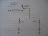
I have this simple circuit in which I want that:
-When it is in State 1 and switches on State 2 are 'ON' it does not affect the circuit, and vice versa.

I thought about diodes but I do not think it would be feasible as I will have about 10-20 signal lamps and implementing them at each switch seems a bit hmmm...

I don't know if any of you brave minds have a simple solution to this!
If you do, it would help me a lot!

Thank you for your time in advance!
 

Arouse1973

Adam
Dec 18, 2013
5,178
Joined
Dec 18, 2013
Messages
5,178
Hello
What do you mean by does not effect the circuit. What do you want it to do?
Adam
 

Kelvingen

Jul 20, 2015
5
Joined
Jul 20, 2015
Messages
5
meaning that, if the switches on state 2 are in the ON state it does not turn on the light if the switch on state 1 is 'OFF' (When state 1 is activated on top).

Here we have the circuit in State 1 and when switches 3 and 4 are turned on the second bulb still turns on even when switch 2 is off.
I do not want this to happen as circuit is in State 1 and not 2.


Imagine the circuit in TWO, The left half and the right half, i.e. state 1 and state 2 respectively.
When either of the states is Activated (from the top toggle switch), I would like it to be independent no matter what happens on the other stage.

Dont know if I explained myself enough for you to visualize :)
 

BobK

Jan 5, 2010
7,682
Joined
Jan 5, 2010
Messages
7,682
Adam,

What he wants is when in state 1 the two switcheson the left control the lamps, and when in state 2 the two switches on the right control them. As is, if both switches are on on either side, the lamps cannot be controlled independently.

IMHO, diodes in series with each switch is a fine solution.

Bob
 

Kelvingen

Jul 20, 2015
5
Joined
Jul 20, 2015
Messages
5
Yes Bob, do you think they are a viable solution in terms of reliability, and not burning out on me especially if I am running high currents, such as 40Amps @12V
 

davenn

Moderator
Sep 5, 2009
14,470
Joined
Sep 5, 2009
Messages
14,470
what do you need the 40A for ?

The globes wont draw 40A unless they are around 500W
and that's a lot of light
 

Arouse1973

Adam
Dec 18, 2013
5,178
Joined
Dec 18, 2013
Messages
5,178
Adam,

What he wants is when in state 1 the two switcheson the left control the lamps, and when in state 2 the two switches on the right control them. As is, if both switches are on on either side, the lamps cannot be controlled independently.

IMHO, diodes in series with each switch is a fine solution.

Bob

Ok got it now Bob.
Thanks
Adam
 

hevans1944

Hop - AC8NS
Jun 21, 2012
4,968
Joined
Jun 21, 2012
Messages
4,968
You will need two diodes for each light with a current rating at least equal to what the light draws. So, if it's a 12 V lamp drawing 1 A and you have forty of them, you need eighty diodes each capable of holding off 12 V and conducting 1 A. A common 1N4001 silicon diode would work for 1A current and hold off 12 V. Higher current would require a different diode. You should not try to place diodes in parallel to increase the current capacity because there is no efficient way to ensure each diode carries the same current.
 

Kelvingen

Jul 20, 2015
5
Joined
Jul 20, 2015
Messages
5
what do you need the 40A for ?

The globes wont draw 40A unless they are around 500W
and that's a lot of light

I dont need 40Amp right now, its for future proofing, the lights are just there as an example, I might have a water pump for example drawing 400watts,

You will need two diodes for each light with a current rating at least equal to what the light draws. So, if it's a 12 V lamp drawing 1 A and you have forty of them, you need eighty diodes each capable of holding off 12 V and conducting 1 A. A common 1N4001 silicon diode would work for 1A current and hold off 12 V. Higher current would require a different diode. You should not try to place diodes in parallel to increase the current capacity because there is no efficient way to ensure each diode carries the same current.

If for example i have 10 bulbs each drawing 1A and 1 drawing 5A do i just need two diodes for that?
Or do I have to make all the diodes in the circuit 5Amp?

Thanks, I really appreciate everyone`s time.
 

Martaine2005

May 12, 2015
5,276
Joined
May 12, 2015
Messages
5,276
Can I ask a question?
Why do you need STATE 1 And 2?

You caould change the top toggle for a normal ON/OFF for both circuits.
And change sw3 and sw4 for 2way switches. Link sw1 to sw3 and sw2 to sw4.

That should be something like a two way switching circuit and all switches work independently.
I think.........

Martin
 

Kelvingen

Jul 20, 2015
5
Joined
Jul 20, 2015
Messages
5
Can I ask a question?
Why do you need STATE 1 And 2?

You caould change the top toggle for a normal ON/OFF for both circuits.
And change sw3 and sw4 for 2way switches. Link sw1 to sw3 and sw2 to sw4.

That should be something like a two way switching circuit and all switches work independently.
I think.........

Martin

I can not, for the simple fact that one of the states will not be physically controlled, but controlled with a software application.
This diagram is just a mock up.
 

Martaine2005

May 12, 2015
5,276
Joined
May 12, 2015
Messages
5,276
I omitted to say sw1 and sw2 too. So wouldn't have worked anyway.:oops:

Back to the diodes then...For now...

Martin
 

Martaine2005

May 12, 2015
5,276
Joined
May 12, 2015
Messages
5,276
one of the states will not be physically controlled, but controlled with a software application.
Ok, in that case you need two input sources and one output on a SPDT switch. State1 constant supply and state2 computer controlled.
Then you can use just two switches for on/off of each circuit regardless of which supply.


Martin
 

Attachments

  • spdt.jpg
    spdt.jpg
    6.9 KB · Views: 64
Last edited:
Top