OK ...
A couple of misconceptions
")
but that's ok cuz you are asking questions and the answers are reasonably straight forward --- never be afraid to ask
My teacher did Two days on Electronics. Only because we asked.
But he said that a cap is two plates separated by a Dielectric. And when the Sine wave (Pulsating DC) when on the Peak the Positive side gains more Protons and become positively Charged. And the same for the Negative only more Electrons.
yes, 2 plates separated by a dielectric
Nothing gains more protons, protons dont come and go from a capacitor plate, bit of wire or a circuit in general.
Its the outer valence electrons of a conductor that are free to move between atoms and slowly make their way around a circuit. Its that movement that is the electrical current.
Note I used the word ... slowly ... this is because electrons DONT rush around a circuit at near the speed of light ... this is another misconception many people have.
Electrons move around a circuit quite slowly in what is called electron drift... its on the order of ~ 1 metre / hr ( partly dependant on the type of metal)
So something having a positive charge just implies the lack of electrons
I was thinking that because of this then you can make both side of the cap Positive by Connecting Both Negative and Positive side of the Cap together so that you have Double the Capacity. The point of this, is to save space or get more out of the cap. \
capacitors dont work that way
in an AC circuit, a capacitor plate can alternate back and forward between positive and negative as the electrons move back and forward as part of the AC cycle
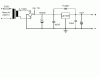
Also somebody said that after a Bridge Rectifier you need a Smoothing Cap of 1,000uf to 1 amp of Draw. Then the Caps for the Voltage Regulator and then a 10uf cap after. What is this cap for?
OK here's a pretty standard 5V regulated PSU....
the 10uF electrolytic on the output is just additional smoothing
Dave