Thermostat with lm35: help finding out the error

joerack

Jun 14, 2016
4
Joined
Jun 14, 2016
Messages
4
Hello all

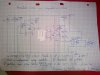
I'm trying to build a thermostat with 2 opamps, the first amplifies the analog voltage and the second as a comparator. the comparator should give me a v output whenever the ref (coming from the voltage divider) is higher than what's coming out from my Lm358 configured as hysteresis comp

so the first part of the circuit works, but measuring from the lm393 I'm always getting -9v

please help

https://www.dropbox.com/s/utah1nbrmgwtfxd/IMG_20160614_092224.jpg?dl=0
 

(*steve*)

¡sǝpodᴉʇuɐ ǝɥʇ ɹɐǝɥd
Moderator
Jan 21, 2010
25,510
Joined
Jan 21, 2010
Messages
25,510
can you post the schematic here? I can see it on dropbox but I can't zoom in on it to see what's going on.
 

joerack

Jun 14, 2016
4
Joined
Jun 14, 2016
Messages
4
I inverted a polarity (duh!)

so I'm getting a constant +4/5v from the first opamp, and a constant 8.45 from the second (obs: I'm not using a 1m pot as in the scheme, but a 100k)
I need to make the comparation work so that when the temp is lower than the voltage divider, nothing comes out of the lm393
 

(*steve*)

¡sǝpodᴉʇuɐ ǝɥʇ ɹɐǝɥd
Moderator
Jan 21, 2010
25,510
Joined
Jan 21, 2010
Messages
25,510
Remember that the LM393 has an open collector output. You will need to add a 2.2k resistor (or similar) from the output to the +ve supply to enable the output to go high.
 

hevans1944

Hop - AC8NS
Jun 21, 2012
4,968
Joined
Jun 21, 2012
Messages
4,968
Expanding on Steve's comment in post #5: The LM393 has an open-collector output that will sink (typically) 16 mA when the output is "low" and will present an open-circuit when the output is "high". To drive the relay coil, you connect one side of the coil to +V and the other side to the LM393 output. A reverse-biased diode across the relay coil is recommended to absorb back-emf produced when the coil is turned off, i.e., LM393 output "high". Make sure your relay coil will operate on 9 V DC at less than 16 mA actuation current!
 

AnalogKid

Jun 10, 2015
3,045
Joined
Jun 10, 2015
Messages
3,045
As noted, a 393 has an open collector output that can only sink current, not source it.

1. IF (big if) the relay coil current is less than 50% of the 393 max rated output current, then it is safe to have the 393 drive the relay coil directly (with an added suppression diode across the coil. IF NOT, then an external driver transistor is needed, and this will change the polarity of the input connections. So, figure out the output first and post an updated schematic, then the input can be straightened out.

ak
 
Top