Voltage Converter or Not?

cjdelphi

Oct 26, 2011
1,166
Joined
Oct 26, 2011
Messages
1,166
http://cyntech.co.uk/downloads/neoway-m590-hardware-design-manual-v1.pdf


The m590 says it's not 5v tolerant 3.9v max or there abouts... but if i run an Arduino and tjis m590 module from a single 18650 it will see around 3.8 - 4.0v

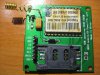
It came in kit form so i'm going to solder or heat gun it then use a usb to ttl converter or WAS (5v usb!)

How about simply tying the grounds but letting the lithium battery power it all?

Bottom line. .. a voltage converter needed ? Thanks
 

Attachments

  • bd322a.jpg
    bd322a.jpg
    180.8 KB · Views: 1,253

Harald Kapp

Moderator
Moderator
Nov 17, 2011
14,271
Joined
Nov 17, 2011
Messages
14,271
It's not about powering the module's Vcc only, it's about voltage levels on the I/O lines, too.
The manual clearly states on page 7:
Because the module uses a 2.85V IO power system, maximum input voltage of all IO
interfaces cannot exceed 3.3V, otherwise the IO may be damaged.
You'll have to use 3.3 V (max.) interface signals, too. Therefore some kind of level shifting is required. See e.g. this discussion.
 

Sunnysky

Jul 15, 2016
573
Joined
Jul 15, 2016
Messages
573
No converter needed.
Input 1 LiPo cell voltage with charger attached.
Serial port 3.3 V logic uC interface.
If using >3.3V logic, then a Schottky .power diode clamp to 3.3V needed for Rx data.
 

Harald Kapp

Moderator
Moderator
Nov 17, 2011
14,271
Joined
Nov 17, 2011
Messages
14,271
If using >3.3V logic, then a Schottky .power diode clamp to 3.3V needed for Rx data.
I see 2 issues here:
  1. clamping worls only with an additional series resistor to drop the residual voltage.
  2. clamping with a Schottky diode (Vdiode ~ 0.3V) to 3.3 V results in 3.6 V on RxD, which is above the limits stated in the manual.

If you decide to take this simple approach, clamp to VCCIO (2.85 V) and use a series resistor (e.g. 1kΩ) to limit the current and to allow for the necessary voltage drop.


Also note the instantaneous current requirement of 2 A!
Ensure your power supply (battery) can deliver this peak current. Add sufficient bypass capacitance (electrolytic, as a rule of thumb 1000µF per 1A of current) to buffer the module. Otherwise you run a risk of unexpected resets of the module due to a brownout.
 

Sunnysky

Jul 15, 2016
573
Joined
Jul 15, 2016
Messages
573
I agree, that's what I meant,moto clamp to internal regulated voltage on Rx chip.
Perhaps series R 100-1K as source impedance will be <100Ω from CMOS driver @5V. use twisted pairs if > 1ft.
2) Normally a LiPo can supply the 3A burst during Tx if charged.
 

Harald Kapp

Moderator
Moderator
Nov 17, 2011
14,271
Joined
Nov 17, 2011
Messages
14,271
2) Normally a LiPo can supply the 3A burst during Tx if charged.
Sounds great, depends on the size of the LiPo, I guess.An 18650 as stated in the op should do. However, it'S a good idea to decouple the arduino and the rf module such that a drop in supply voltage caused by a spike in current by one of them doesn't affect the other:
upload_2016-8-1_18-38-17.png
Thus you have
  • decoupling (D1, D2)
  • buffering (C1, C2)
  • voltage reduction (D1, D2)
Component values are just a suggestion.
 

Sunnysky

Jul 15, 2016
573
Joined
Jul 15, 2016
Messages
573
the board looks as though it already has it with 10uF tantalum and diode, no?

I presumed if an Arduino was being used, it would have a separate supply =7V and onboard 5V so this board has a dedicated LiPo cell with a common ground.
 

cjdelphi

Oct 26, 2011
1,166
Joined
Oct 26, 2011
Messages
1,166
I'm not sure how to go about it hence the question...

I was simply going to power it directly so you think 2 cells and a voltage reg to 5v is better than feeding it a single 18650 cell if around 4.10v?

How about a 3v zener?
 

Sunnysky

Jul 15, 2016
573
Joined
Jul 15, 2016
Messages
573
the board needs 1 LiPo. 3.3~4.5 is spec'd
the arduino needs 2 LiPo with 5V LDO with <1V dropout
definitely not a 2A Zener.
ok?
 
Top