What are specs on this cap?

Stamey

Apr 28, 2023
44
Joined
Apr 28, 2023
Messages
44
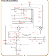
The footswitch terminals, on the junction block, on the left, measures 960 ohms, regardless of whether the foot switch is connected. The foot switch tests 1M ohms and 0.1 ohms, and works properly, as if I press it with the power on, KM1 activates and locks on.
Tech support said the remove the foot switch from the equation first thing. I believe that the foot switch is wired in parallel with the start switch, as once KM1 latches, it is no longer needed.

Thanks,
Chris
 

kellys_eye

Jun 25, 2010
6,512
Joined
Jun 25, 2010
Messages
6,512
Again, with the power off:

Measure from 1-2 and, at the same time, press the red STOP button. With the red STOP button pressed you should read open-circuit. Is this the case?

Then measure from 15-20 then 14-22. Let me know the result.
 

Attachments

  • Screenshot from 2024-01-24 22-05-11.png
    Screenshot from 2024-01-24 22-05-11.png
    53.3 KB · Views: 3

Stamey

Apr 28, 2023
44
Joined
Apr 28, 2023
Messages
44
I have found I am also dealing with inductive voltage, as I found 10VAC on wire 6, even after disconnecting it from all components except the junction block. I disconnected one side of the junction block and still had 8VAC on the two running to the rectifier and Bend setting switch, SA2, but disconnected from both. I removed the two 6 wires from the bundle they were zipped tied in with other wires and hung them outside of the machine in order to get to 0VAC on those wires. I don't know how much difference this makes, but it is something to be considered as we troubleshoot.
1-2, with stop pressed: OPEN
1-2 without Stop pressed: 959 Ohms
15-20 without Stop pressed: Open, Stop pressed: 0.3 Ohms
14-22 without Stop pressed: Open, Stop pressed: .02 Ohms

Thanks,
Chris
 

kellys_eye

Jun 25, 2010
6,512
Joined
Jun 25, 2010
Messages
6,512
as I found 10VAC on wire 6,
Measured with respect to what? And, with power OFF, how is this possible?

Disconnect 20 and 21 (DC out of the rectifier ZL2) and with power on and NOTHING pressed, what do you measure at the + and - terminals of ZL2?
 

Stamey

Apr 28, 2023
44
Joined
Apr 28, 2023
Messages
44
The 10VAC found on wire 6 is with the power on, no buttons pressed. I was trying to figure out why I have voltage on wires that should have nothing on them at a given state.

20/21 on ZL2, power on, nothing pressed: 12.88 VDC

Thanks,
Chris
 

kellys_eye

Jun 25, 2010
6,512
Joined
Jun 25, 2010
Messages
6,512
The 10VAC found on wire 6 is with the power on, no buttons pressed.
Measured with respect to WHAT? Where are your meter probes when you measure this?

Did you disconnect 20/21 and then measure at the +/- terminals of the rectifier? DC.

Disconnect leads 0 and lead 6 from the rectifier and measure the voltage on those leads (AC).
 

Stamey

Apr 28, 2023
44
Joined
Apr 28, 2023
Messages
44
The 10VAC was measured from Wire 6 to ground.
Sorry, I don't remember about 20/21. I just measured again, 20/21 disconnected, and get 30VDC from the rectifier terminals.


Wires 0/6 disconnected from the rectifier: 38.4VAC.

Thanks,
Chris
 
Last edited:

kellys_eye

Jun 25, 2010
6,512
Joined
Jun 25, 2010
Messages
6,512
The 10VAC was measured from Wire 6 to ground.
No. When measuring any AC Voltage you must put your meter negative lead on the mains Neutral i.e. wire 0. Measure the AC using the red probe at the relevant points asked.

With all the wiring back to normal, disconnect 20 and 21 from the bridge rectifier. Power up and see if the magnet coil is still pulling.

I'm suspicious of the methods you are using to report the voltages asked for. This could result in me determining problems incorrectly. Given I'm 'confused' at the moment only makes me more sure your measurements aren't right.

Are you setting your meter to read AC when asked for AC voltages? Same for DC?
 

Stamey

Apr 28, 2023
44
Joined
Apr 28, 2023
Messages
44
When you say "With all the wiring back to normal", do you mean I should be re-soldering the caps and reinstalling the board back into the machine? This is the only way that the magnet will get power.
I go from a leg to ground so that I don't get the voltage from the other leg involved in the measurement, since I don't have a neutral with the 220VAC in this machine. You are saying this is wrong?

Thanks,
Chris
 

Stamey

Apr 28, 2023
44
Joined
Apr 28, 2023
Messages
44
When you say "With all the wiring back to normal", do you mean I should be re-soldering the caps and reinstalling the board back into the machine? This is the only way that the magnet will get power.
I go from a leg to ground so that I don't get the voltage from the other leg involved in the measurement, since I don't have a neutral with the 220VAC in this machine. You are saying this is wrong?
Yes, I am setting the meter to AC or DC, as applicable.

Thanks,
Chris
 

kellys_eye

Jun 25, 2010
6,512
Joined
Jun 25, 2010
Messages
6,512
This is the only way that the magnet will get power.
No it's not. It gets power from ZL1 as well.
since I don't have a neutral with the 220VAC in this machine.
Yes you do. It might not be known as neutral in the USA (you use 'hot' and 'ground') but check the wiring schematic. the 'N' mains input (neutral) connects to the '0' wires and this is what should be used as your reference 'ground' when measuring AC voltages anywhere in the machine.
When you say "With all the wiring back to normal",
Basically, yes. We need to start from a point we can both agree on since there is clearly some misunderstanding - as per the AC measurement I mention - and there may have been other 'inconsistencies' as a result. Let's start from 'square one' and I'll list the tests you need to make - both un-powered and with power on - to locate the fault precisely.
 

kellys_eye

Jun 25, 2010
6,512
Joined
Jun 25, 2010
Messages
6,512
With everything back in place and with the power OFF test the following (use your meter on the 'continuity' setting i.e. 'beeper')

0-1 (around 900 ohms)
1-2 (around 900 ohms)
2-3 (open)
2-5 (open)
2-6 (open)
2-7 (short)
2-8 (short)
2-9 (open)
12-13 (short)
12-14 (short)
14-22 (short)
15-20 (short) - report any readings that DO NOT match what I've listed here.

Then turn the power on (rocker switch only) and measure the following voltages: note - put your meter to AC and the probes on the points listed below:

0-1 (240VAC)
10-11 (12V AC)

Switch to DC and put black probe on 12, red probe on 15 you should measure a DC voltage. What is it?

That'll do for now. Let me know the results.
 

Stamey

Apr 28, 2023
44
Joined
Apr 28, 2023
Messages
44
With everything back in place and with the power OFF test the following (use your meter on the 'continuity' setting i.e. 'beeper')

0-1 (around 900 ohms)
1-2 (around 900 ohms)
2-3 (open)
2-5 (open)
2-6 (open)
2-7 (short)
2-8 (short)
2-9 (open)
12-13 (short)
12-14 (short)
14-22 (short)
15-20 (short) - report any readings that DO NOT match what I've listed here.

Then turn the power on (rocker switch only) and measure the following voltages: note - put your meter to AC and the probes on the points listed below:

0-1 (240VAC)
10-11 (12V AC)

Switch to DC and put black probe on 12, red probe on 15 you should measure a DC voltage. What is it?

That'll do for now. Let me know the results.
Resistance:
0-1 = 338 ohms at power switch.
2-8 = 9 ohms
14-22 = Open

Power on, nothing else:
Voltage:
0-1 = 212.5 VAC
10-11 = 14.1 VAC
12-15 = 12.86 VDC

Thanks,
Chris
 

kellys_eye

Jun 25, 2010
6,512
Joined
Jun 25, 2010
Messages
6,512
0-1 looks ok it is the resistance of the mains transformer primary winding and we know this is working because 10-11 is ok.
2-8 is ok, it's the resistance of the thermal cutout.
10-11 is also ok. The stated secondary AC is 12V but is commonly higher by up to 10%. Irrelevant at this stage.

Now, wit nothing pressed, measure DC volts between 20 and 22
then the AC at ZL1 (between wires 0 and 6)

Report findings.
 

Stamey

Apr 28, 2023
44
Joined
Apr 28, 2023
Messages
44
20-22, nothing pressed, power on: 112VDC
0-6: 2.5VAC

Thanks,
Chris
 

kellys_eye

Jun 25, 2010
6,512
Joined
Jun 25, 2010
Messages
6,512
112V DC at 20/21 seems ok as, with K1 energised, AC flows via contacts KM1 and C4 to the rectifier ZL2. This will provide the LOW clamping force at the magnet coil.

I presume you're measuring 2.5VAC at 0/6 when power is applied but no button pressed?

If you operate the toggle switch ( lid down, limit switch operating) the DC voltage at 20/21 should increase to 200+ volts. Please confirm.
 

Stamey

Apr 28, 2023
44
Joined
Apr 28, 2023
Messages
44
That's the problem. I have not pressed the start button yet, but I have 112 VDC to the magnet with power on. This means I cannot move the clamping leaf (different from the bending leaf) to put parts in or take them out. There should be 0 VDC going to the magnet until I press Start, unless I have flipped the toggle switch from "Clamping for bending" to "continuous light clamping" . I do not know what the voltage should be in the "continuous light clamping" position. I assume it should be some low number, 30-50 VDC because at 112 VDC nothing can be moved by a regular human.

Yes, on 0/6, nothing pressed, power on: 2.5VAC.
20-22, nothing pressed, power on: 112VDC
20-22, power on, after Start pressed (KM1 engaged): 117 VDC
20-22, power on, after start button pressed (KM1 engaged), bending leaf moved (KM2 engaged): 244 VDC

You mentioned 20/21 in the last post. I have to assume that was a typo. Please confirm it is not and I will measure that.

Thanks,
Chris
 
Last edited:

kellys_eye

Jun 25, 2010
6,512
Joined
Jun 25, 2010
Messages
6,512
You mentioned 20/21 in the last post. I have to assume that was a typo.
My bad. NOT a typo in that context - that's what I meant when I said 20/22, sorry.

What is the voltage at 20/21 with power ON?
What is the voltage at 20/21 with the START button pressed?

That's the problem. I have not pressed the start button yet, but I have 112 VDC to the magnet with power on.
Yes, on 0/6, nothing pressed, power on: 2.5VAC.
That 2.5VAC is 'as good as nothing' so with nothing on the rectifier ZL2 there should be NO DC coming out of it at 20/21 thus no DC to the holding coil.

Remove wires 20/21 from the rectifier ZL2 and see if the holding coil is still on.
 

Stamey

Apr 28, 2023
44
Joined
Apr 28, 2023
Messages
44
20/21, power on: 113.2 VDC
20/21 with start pressed, also: 119.6
Also checked 20/21 with start pressed and bending leaf lifted: 250VDC
With start pressed, KM1 holding, removal of the 20 and 21 wire from rectifier make no difference to KM1, but the magnet releases after ~two seconds.

After releasing KM1 by pressing the Stop button, and connecting either (not both at the same time) 20 or 21, the magnet begins pulling again. I then reconnected both 20 and 21 to the rectifier again.

Thanks,
Chris
 
Last edited:

Stamey

Apr 28, 2023
44
Joined
Apr 28, 2023
Messages
44
Well, my magnet has a short, so that is the problem and I am trying to figure out what I am going to do with it.

Chris
 
Top