12-Bit Programmable Contactless Encoder Module
- Rajkumar Sharma
- 162 Views
- easy
- Tested
- SKU: EL137669
- Quote Now
- 0 Likes

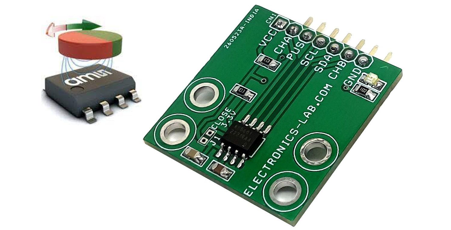
The 12-Bit programmable contactless encoder project presented here is based on AS5601 chip. This is an easy-to-program magnetic rotary position sensor module with incremental quadrature (A/B) and 12-bit digital outputs. Additionally, the PUSH output indicates fast airgap changes between the AS5601 and magnet which can be used to implement a contactless pushbutton function in which the knob can be pressed to move the magnet toward the AS5601 chip. This module is designed for contactless encoder applications, and its robust design rejects the influence of any homogenous external stray magnetic fields. Based on planar Hall sensor technology, this device measures the orthogonal component of the flux density (Bz) from an external magnet. The industry-standard I²C interface supports user programming of non-volatile parameters in the AS5601 without requiring a dedicated programmer. The AS5601 also provides a smart low-power mode which automatically reduces power consumption.
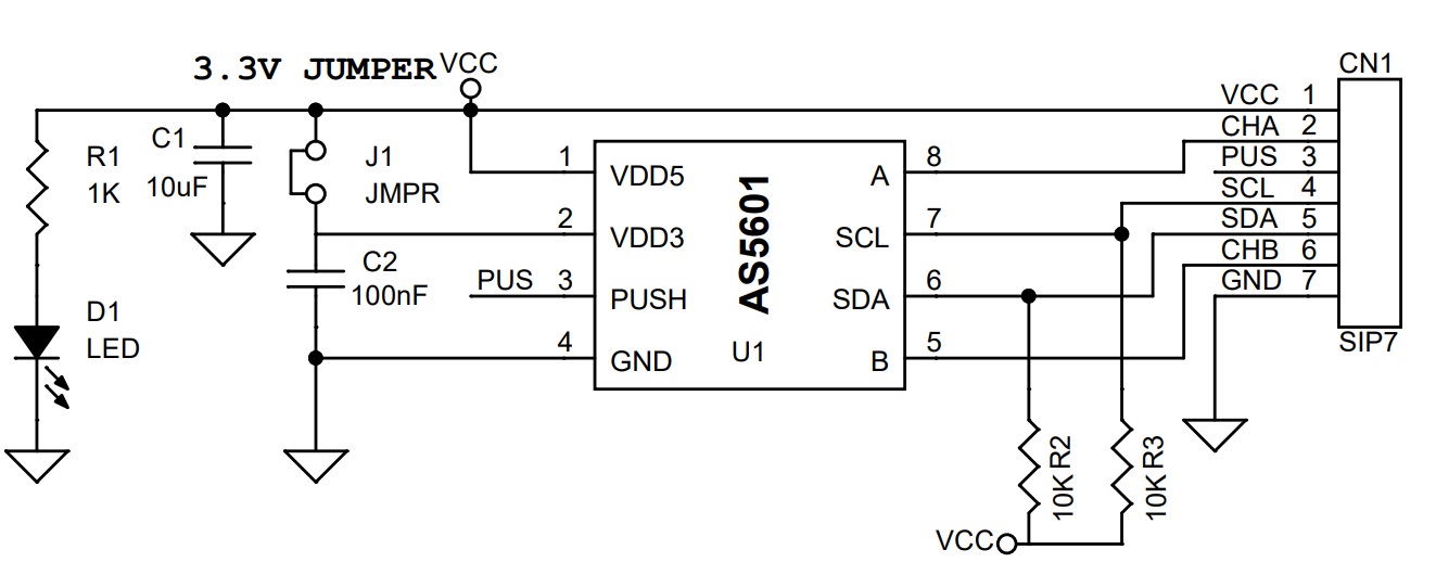
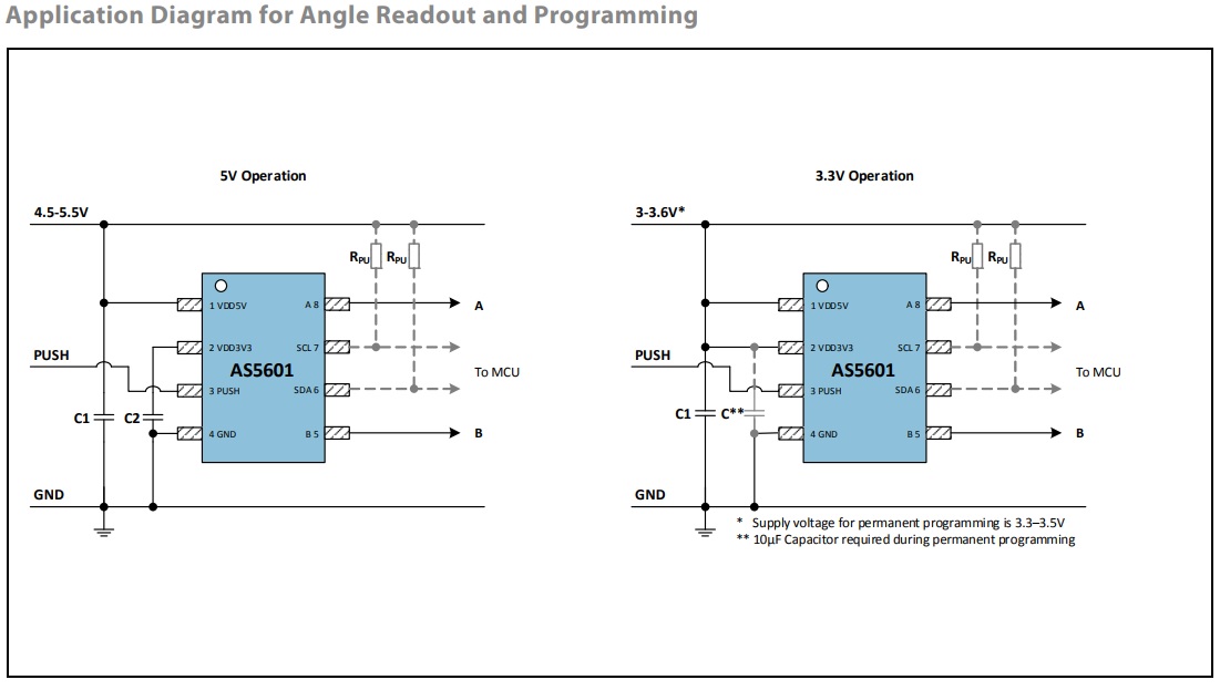
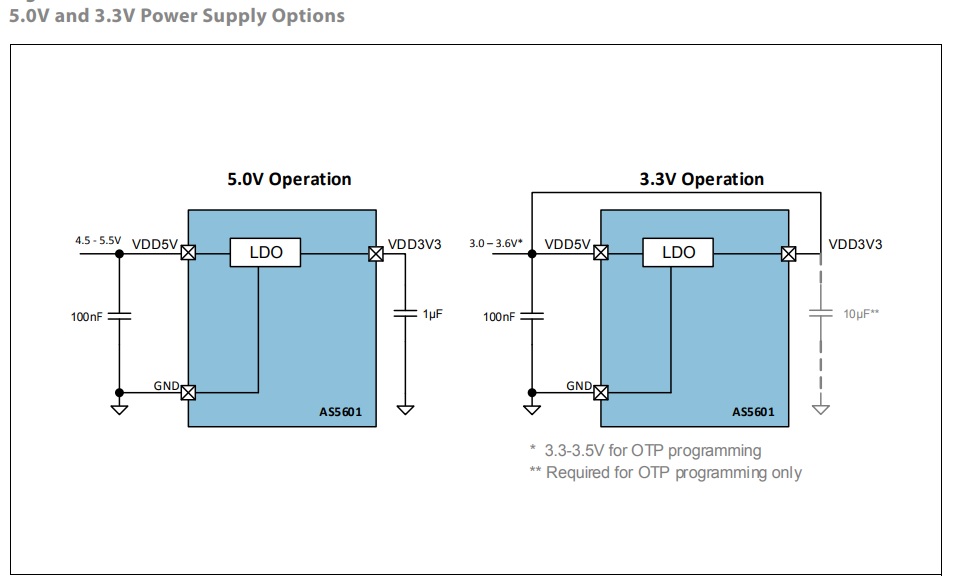
Power Management: The AS5601 is powered from a 5.0V supply using the on-chip LDO regulator, or it can be powered directly from a 3.3V supply. In 3.3V operation, the VDD5V and VDD3V3 pins must be tied together using Jumper J1. VDD is the voltage level present at the VDD5V pin.
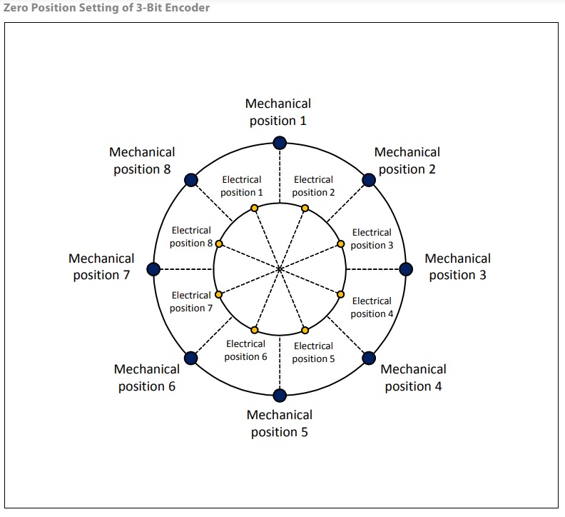
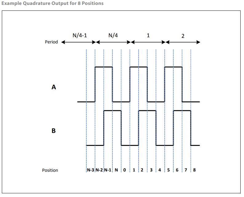
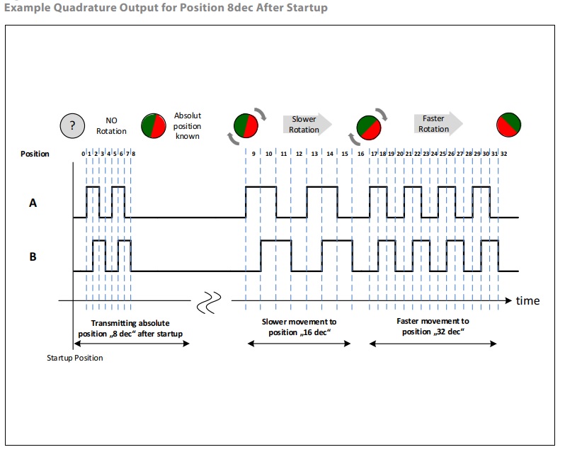
Absolute Position Feature for Quadrature Output The absolute angular position of the magnet is transmitted on the quadrature output of the position sensor after startup. By counting these pulses after startup, the absolute position within one turn of an encoder knob is known without separate initialization as shown in the Figures below.
I2C Mode: Refer to the datasheet of AS5601 chip for more information about I2C programming.
Features
- Power Supply 5V or 3.3V DC
- PCB Solder Jumper for 5V or 3.3V Supply Selection
- Contactless angle measurement insensitive to dust and dirt
- Simple user-programmable zero position and device configuration
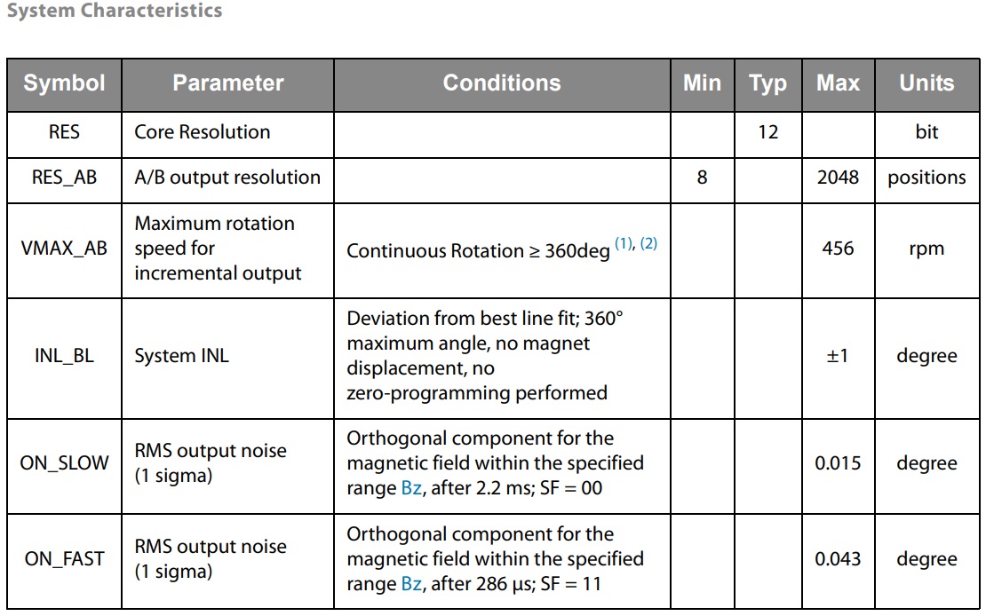
- Quadrature output configurable from 8 up to 2048 positions
- Pushbutton output by detecting sudden airgap changes
- Automatic entry into low-power mode
- Automatic magnet detection
- Flexible choice of the number of A/B pulses per revolution
- Simple programming
- 4 x 3 mm Mounting Holes
- PCB Dimensions 29.21 x 27.31 mm
Applications
- The AS5601 Module is ideally suited for:
- Encoder replacement
- Contactless rotary knobs with push buttons
- Other angular position measurement solutions
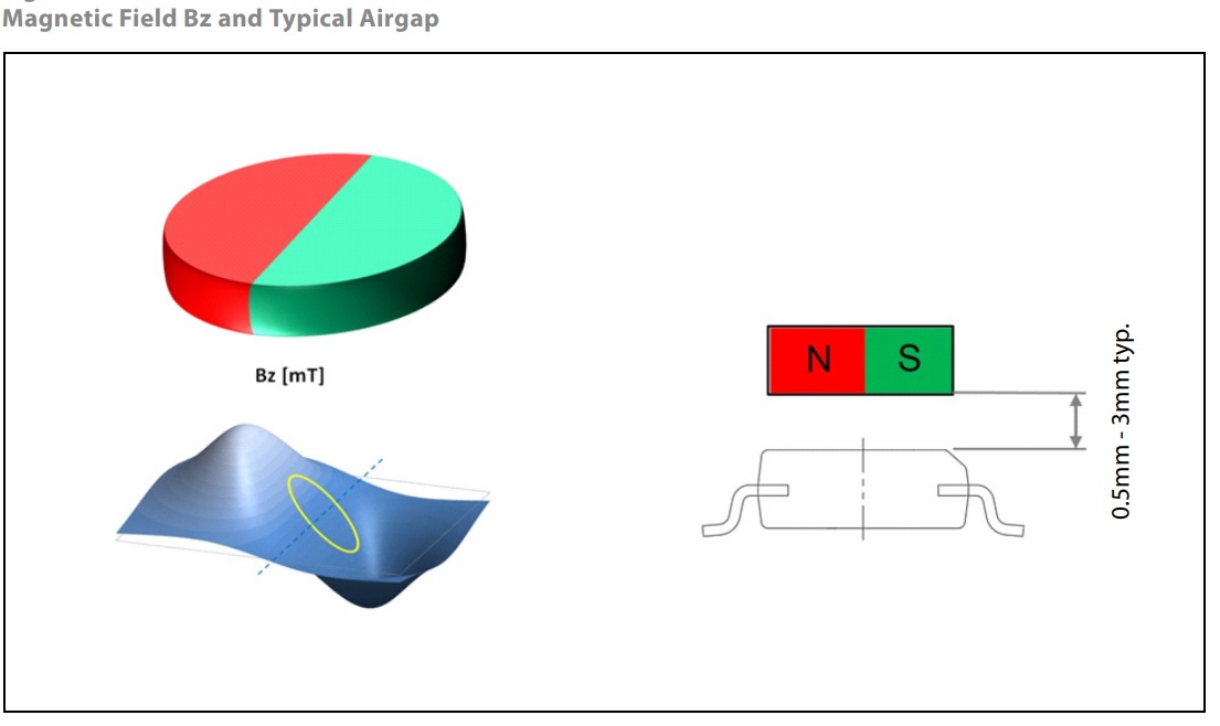
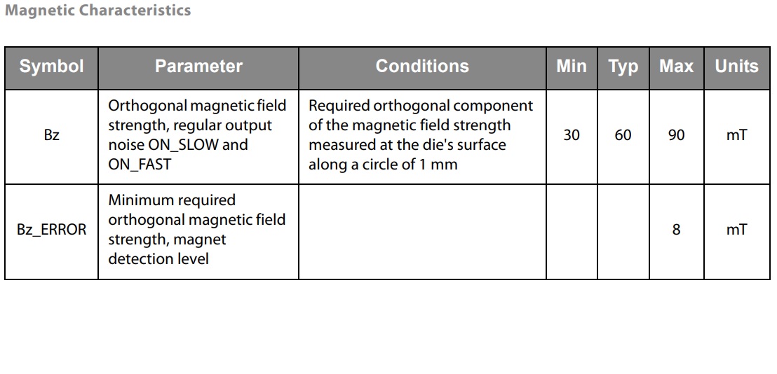
Magnet Requirements
The AS5601 requires a minimum magnetic field component Bz perpendicular to the sensitive area on the chip. The center of the sensitive area is in the center of the package. Along the circumference of the Hall element circle the magnetic field Bz should be sine-shaped. The magnetic field gradient of Bz along the circle’s radius should be in the linear range of the magnet to eliminate displacement error by the differential measurement principle. The typical airgap is between 0.5 mm and 3 mm, and it depends on the selected magnet. A larger and stronger magnet allows a larger airgap. Using the AGC value as a guide, the optimal airgap can be found by adjusting the distance between the magnet and the AS5601 so that the AGC value is in the centre of its range. The maximum allowed displacement of the rotational axis of the reference magnet from the centre of the package is 0.25 mm when using a magnet with a diameter of 6mm.
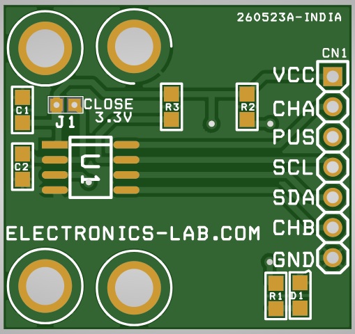
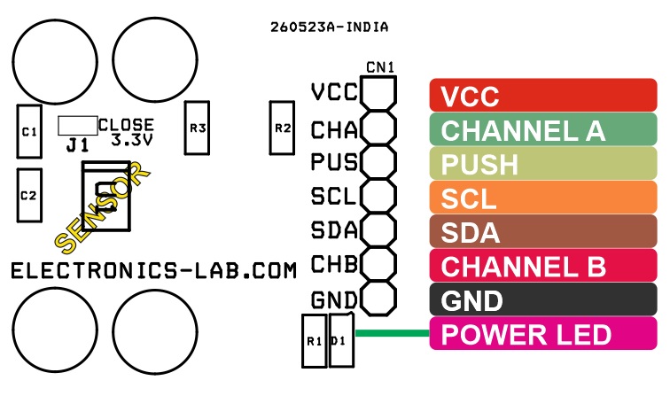
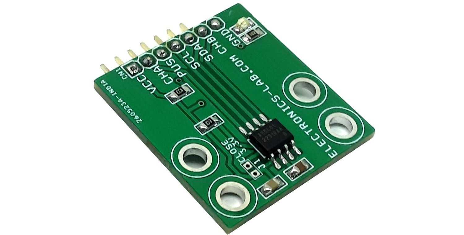
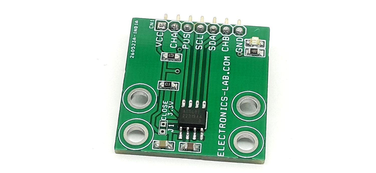
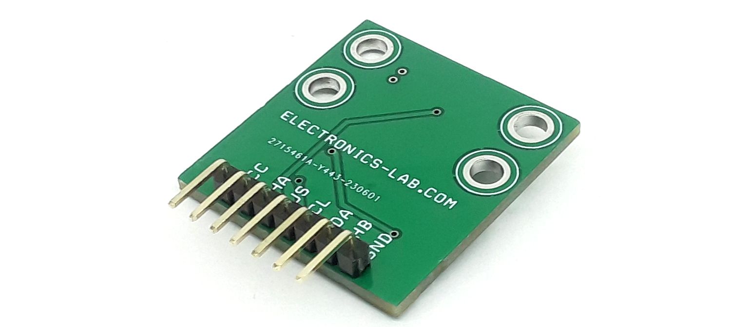
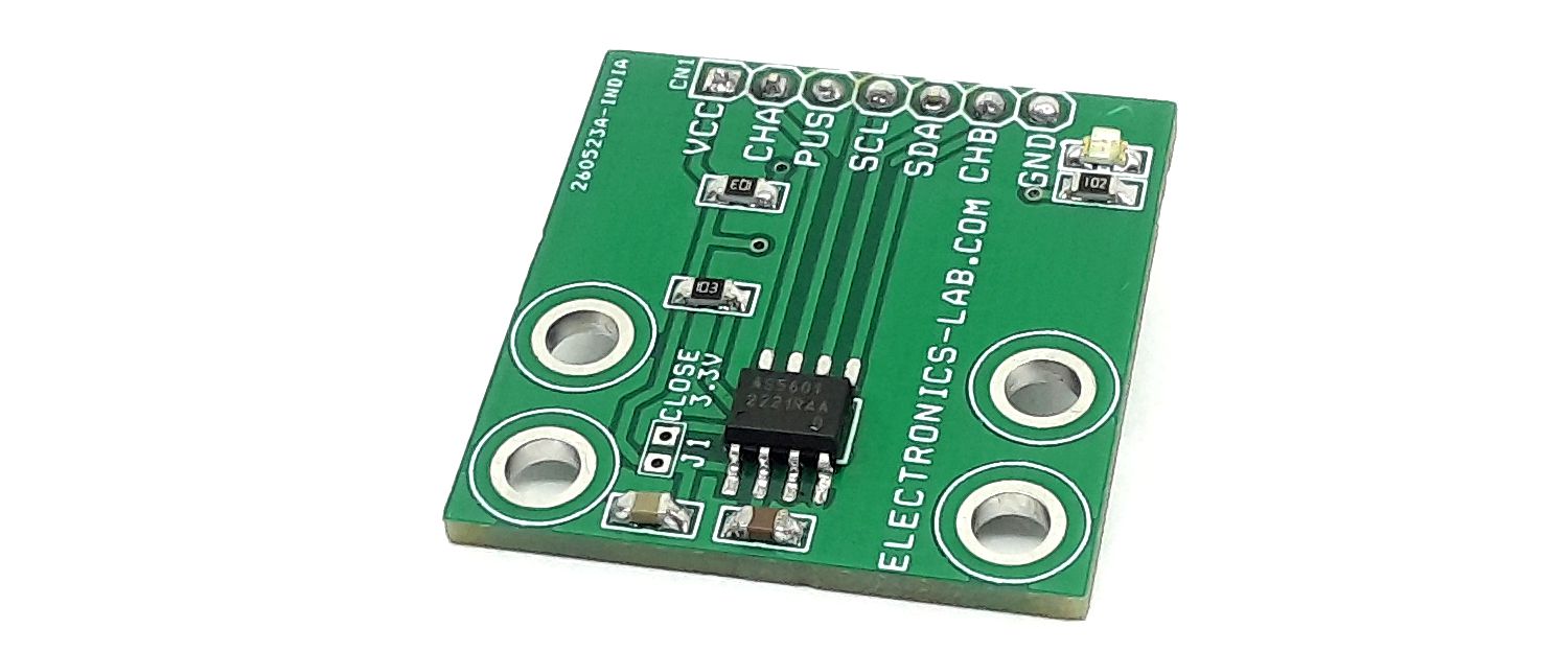
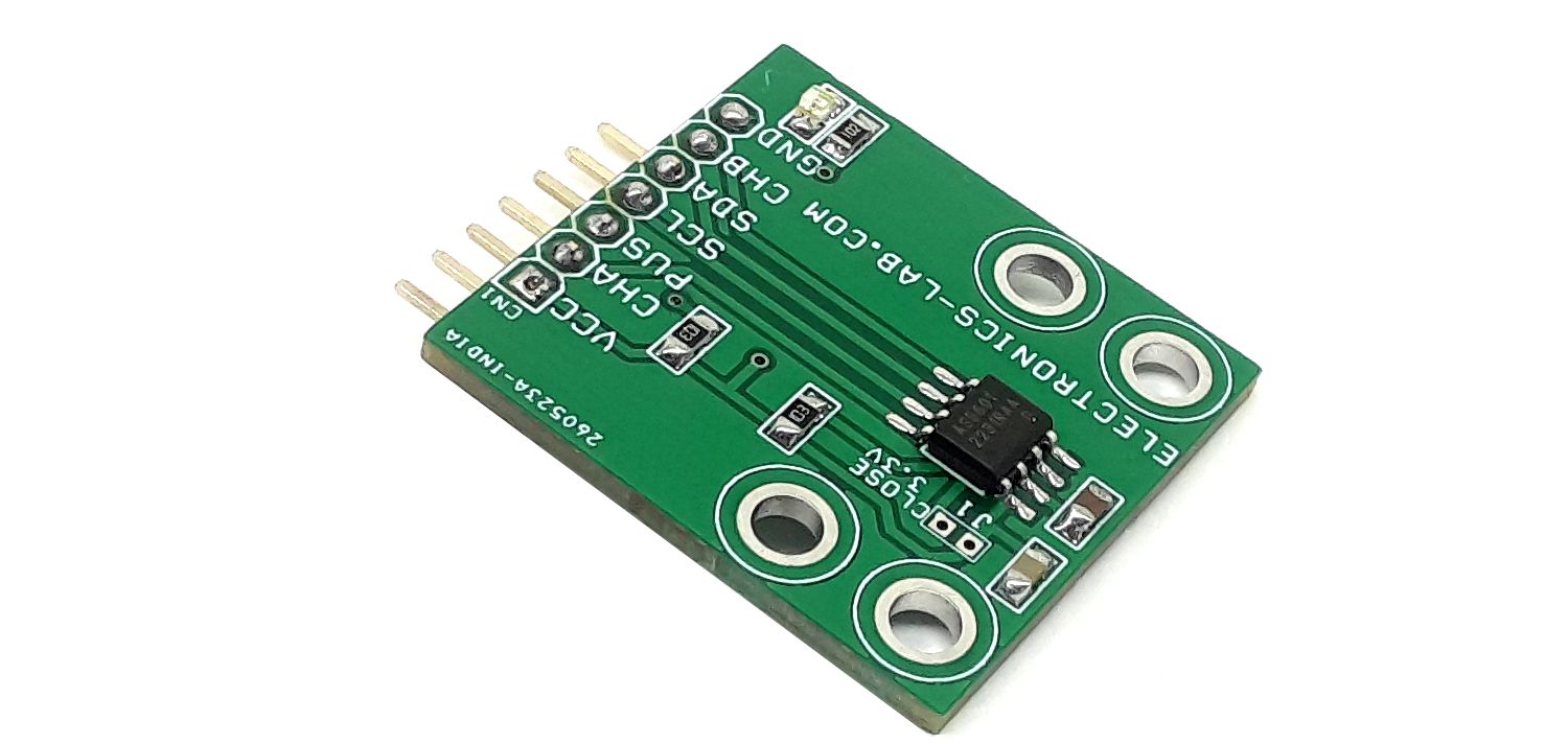
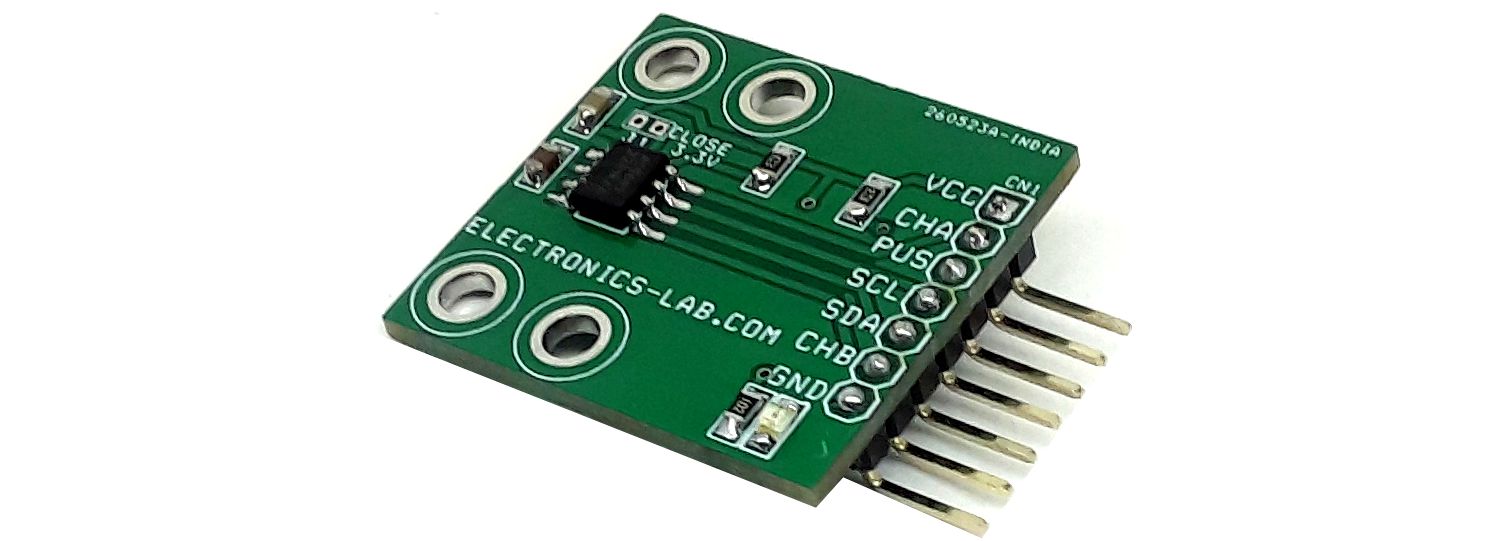
Connections and Other Details
- CN1: Pin 1 = VCC 5V or 3.3V, Pin 2 = Quadrature incremental signal A, Pin 3 = Push Digital Output (Contactless Push Button Function Output, Pin 4 = I2C Clock (Digital Input), Pin 5 = SDA I2C Data (Digital Input and Output), Pin 6 = Quadrature incremental signal B, Pin 7 = GND
- Jumper: PCB Solder Jumper VCC 3.3V = Jumper Closed, VCC 5V = Jumper Open
- D1: Power LED
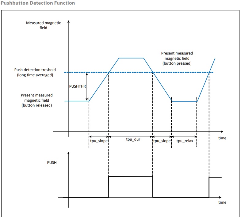
Pushbutton Detection
The AS5601 implements a pushbutton detection function through a dynamic and relative measurement of the orthogonal magnetic field strength. This pushbutton detection function drives the PUSH output pin high when the AS5601 detects a fast increase of the magnetic field (decrease of the airgap between the magnet and the AS5601). After a fast decrease in the magnetic field, the PUSH output is driven low.
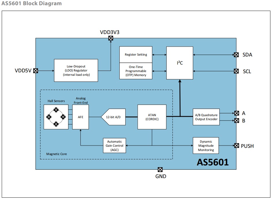
The AS5601 is a Hall-based rotary magnetic position encoder that converts the magnetic field component perpendicular to the surface of the chip into voltages which are used to produce incremental A/B outputs and absolute position indication in registers that can be read over an industry-standard I²C bus. The analog signals from the Hall sensors are first amplified and filtered before being converted by the analog-to-digital converter (ADC) into binary data. The output of the ADC is processed by the hardwired CORDIC block (Coordinate Rotation Digital Computer) to compute the angle and magnitude of the magnetic field vector. The intensity of the magnetic field is used by the automatic gain control (AGC) to adjust the amplification level to compensate for temperature and magnetic field variations. The angle value provided by the CORDIC algorithm is used by the internal logic to generate the incremental quadrature signals A and B. The magnitude and AGC value is dynamically monitored and generates the PUSH output for fast changes of the airgap between the magnet and the AS5601. Very slow changes are suppressed to provide a robust and reliable pushbutton output that tolerates temperature variation and magnet degradation. The AS5601 is programmed through an industry-standard I²C interface to write an on-chip one-time programmable (OTP) memory. This interface can be used to program a zero angle and to configure the chip.
I²C Interface
The AS5601 supports the 2-wire Fast-mode Plus I²C-slave protocol in device mode, in compliance with the NXP Semiconductors (formerly Philips Semiconductors) specification UM10204. A device that sends data onto the bus is a transmitter and a device receiving data is a receiver. The device that controls the message is called a master. The devices that are controlled by the master are called slaves. A master device generates the serial clock (SCL), controls the bus access, and generates the START and STOP conditions that control the bus. The AS5601 always operates as a slave on the I²C bus. Connections to the bus are made through the open-drain I/O lines SDA and the input SCL. Clock stretching is not included. The host MCU (master) initiates data transfers. The 7-bit slave address of the AS5601 is 0x36 (0110110 in binary).
Supported Modes
- Random/Sequential read
- Byte/Page write
- Automatic increment (ANGLE register)
- Standard-mode
- Fast-mode
- Fast–mode Plus
The SDA signal is the bidirectional data line. The SCL signal is the clock generated by the I²C bus master to synchronize sampling data from SDA. The maximum SCL frequency is 1 MHz Data is sampled on the rising edge of SCL.
Schematic
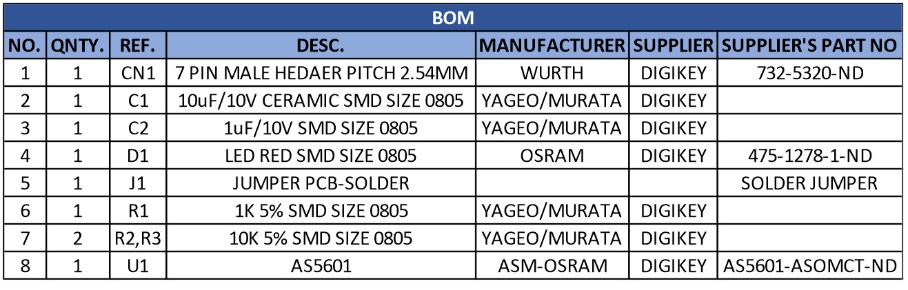
Parts List
| NO. | QNTY. | REF. | DESC. | MANUFACTURER | SUPPLIER | PART NO |
|---|---|---|---|---|---|---|
| 1 | 1 | CN1 | 7 PIN MALE HEDAER PITCH 2.54MM | WURTH | DIGIKEY | 732-5320-ND |
| 2 | 1 | C1 | 10uF/10V CERAMIC SMD SIZE 0805 | YAGEO/MURATA | DIGIKEY | |
| 3 | 1 | C2 | 1uF/10V SMD SIZE 0805 | YAGEO/MURATA | DIGIKEY | |
| 4 | 1 | D1 | LED RED SMD SIZE 0805 | OSRAM | DIGIKEY | 475-1278-1-ND |
| 5 | 1 | J1 | JUMPER PCB-SOLDER | SOLDER JUMPER | ||
| 6 | 1 | R1 | 1K 5% SMD SIZE 0805 | YAGEO/MURATA | DIGIKEY | |
| 7 | 2 | R2,R3 | 10K 5% SMD SIZE 0805 | YAGEO/MURATA | DIGIKEY | |
| 8 | 1 | U1 | AS5601 | ASM-OSRAM | DIGIKEY | AS5601-ASOMCT-ND |
Connections
Function Diagrams
System Characteristics
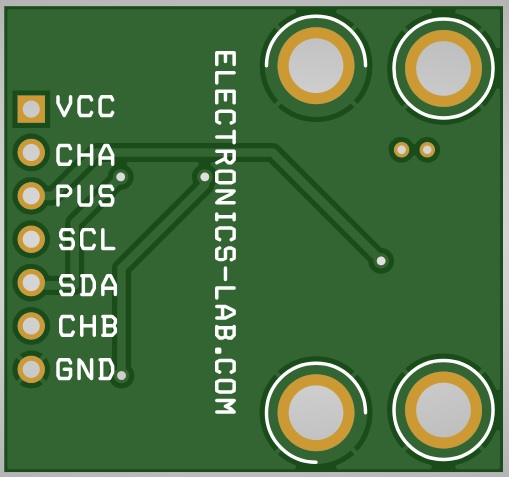
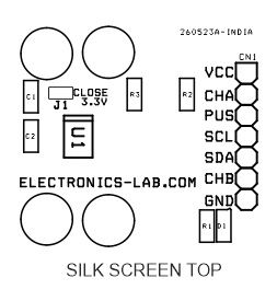
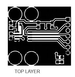
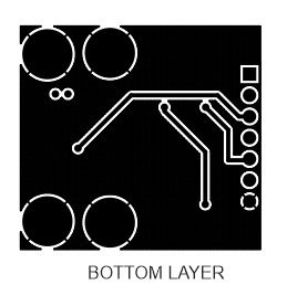
Gerber View
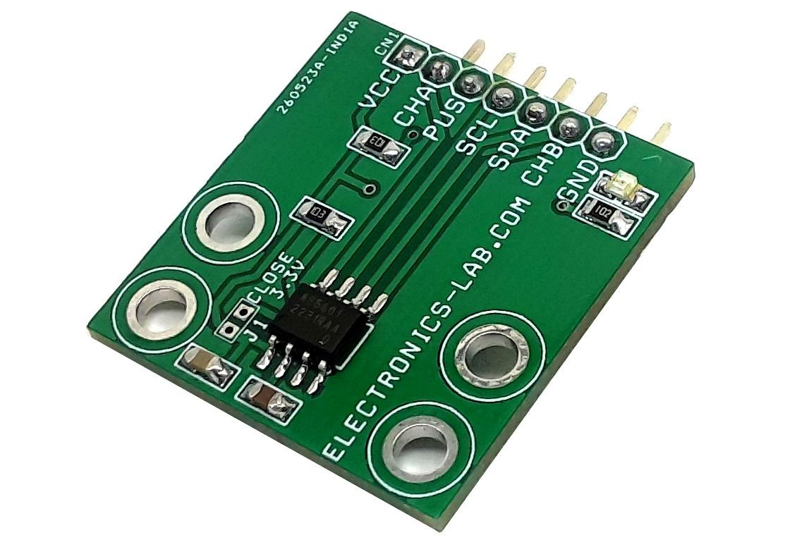
Photos
Video
AS5601 Datasheet
PCB