
Arduino DIY Photo Frame using ST7735 1.8″ TFT Display
- Nick Koumaris
- http://educ8s.tv
- info@educ8s.tv
- 10.556 Views
- moderate
- Tested
- 0 Likes

Electronics has transited from a work meant for well-trained engineers to something which is dabbled into by people in other fields especially in Arts and related fields. The introduction of platforms like Arduino (which was created for reasons like this), has been one of the main facilitators of this trend which has produced diverse forms of electronics embedded art pieces, from interactive paintings to animatronic sculptures. For today’s tutorial, we will build our own work of “art” – a digital Photo Frame. Photoframes are used to display pictures or artworks and are made from wood, metal and several synthetic material. They were created to hold just one picture/artwork but with digital photo frames, you could have more than one picture stored on the photo frame, switching between them at desired intervals.
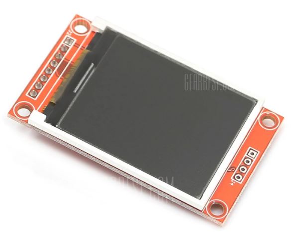
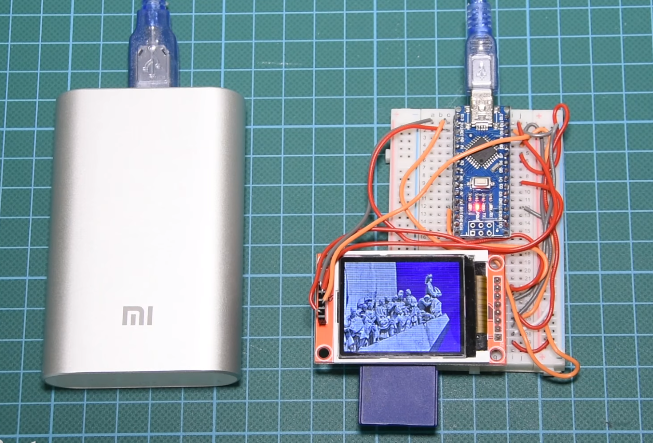
Digital Photo frames are usually made up of four main components; a display/screen, a storage device, a microcontroller or microprocessor, and a power supply. For today’s tutorial, we will use the 1.8″ ST7735 based, color TFT as our display and the Arduino nano as the microcontroller. The TFT display is a 1.8″ display with a resolution of 128×160 pixels and can display a wide range of colors ( full 18-bit color, 262,144 shades!). The display uses the SPI protocol for communication and has its own pixel-addressable frame buffer which means it can be used with all kinds of microcontrollers and you only need 4 IO pins. The display module also comes with an SD card slot which we will use as the storage device for this project.
Beside just building the digital photo frame, at the end of this tutorial, you would have also learned how to use the SD card slot on the 1.8″ TFT display module for other projects.
Required Components
The following components are required to build this project;
As usual, the specific components used for this tutorial can be bought via the links attached.
Schematics
The ST7735 1.8″ TFT display is made up of two set of header pins. The first one at the top consists of 4 pins and are used to interface the SD card slot at the back of the display.
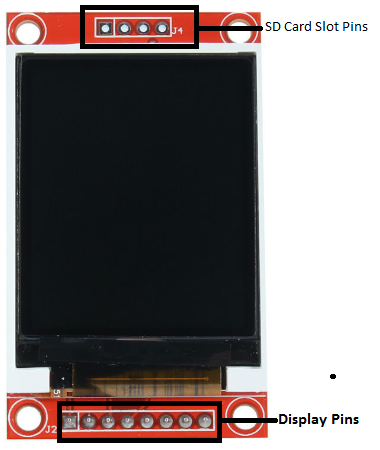
The second set of headers below the screen represent the pins for driving the display itself. However, the SD card slot and the display, both use the SPI protocol for communications with the MCU so they will be connected to the same pins on the Arduino nano. The only difference will be the CS/SS pin as each of them will be connected to a different pin.
Connect the components as shown in the schematics below.
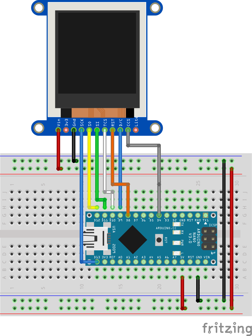
For this schematic, we used the Fritzing model of the ST7735 1.8″ TFT display and the arrangement of the pins is slightly different from that of our display. This model has the pins of the SD card slot and the display merged together breaking out only their CS/SS pins.
To make the connections easier to follow, here is a breakdown.
Arduino - SD Card Slot
D11 - MOSI/SI
D12 - MISO/SO
D13 - SCK
D4 - CS/SS
GND -GND
5V - VIN
The connections for the display side of the TFT is almost the same as the one for the SD card side of the display.
Arduino - 1.8" TFT
D11 - MOSI
D12 - MISO/SO
D13 - SCK
D10 - CS/SS
D8 - RST
D9 - DC
GND -GND
5V - VIN
Go over the schematics one more time to be sure everything is as it should be. More on the use of the 1.8″ TFT display was covered in a previous tutorial here.
Preparing the bitmaps
The images that will be displayed on the TFT has to be in a bitmap format, thus before the images are copied to the SD card, we need to convert them to the recognizable bitmap form. To do this, I used the free Paint.net software (for windows) but you can use any other image editing software.
Load the images into the software one by one and use the resize tool to reduce its resolution and size to that (160×128 pixels) of the 1.8″ TFT display.
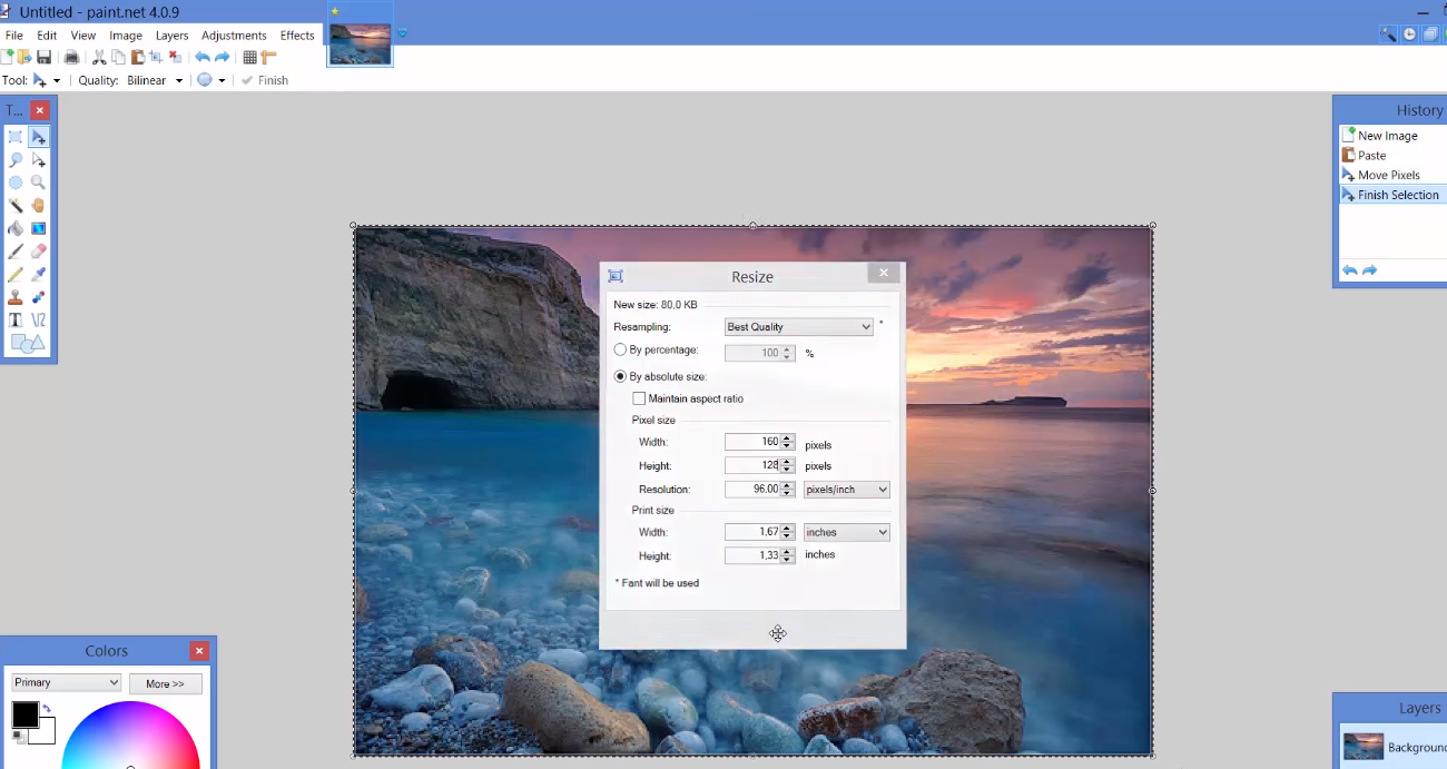
With this done, save the image on the SDcard with a .bmp extension.
Code
The code for this project is a slightly modified version of the SPI TFT bitmap example shipped with the ST7735 library by Adafruit. Thus the code for this tutorial is heavily reliant on the Adafruit ST7735 and GFX libraries.
To do a quick breakdown of the code, we start by including the libraries that we will use, which include the Adafruit libraries mentioned above, the SPI library and the SD.h library.
//Modified by Nick Koumaris
//info@educ8s.tv
#include <Adafruit_GFX.h>    // Core graphics library
#include <Adafruit_ST7735.h> // Hardware-specific library
#include <SPI.h>
#include <SD.h>
With this done, we declare the pins of the Arduino to which the CS pins of the SD card slot and the TFT are connected and also create an object of the Adafruit ST7735 library with the declared pins passed on as arguments.
#define TFT_CS  10  // Chip select line for TFT display
#define TFT_RST  8  // Reset line for TFT (or see below...)
#define TFT_DC   9  // Data/command line for TFT
#define SD_CS    4  // Chip select line for SD card

Adafruit_ST7735 tft = Adafruit_ST7735(TFT_CS, TFT_DC, TFT_RST);
Next is the void setup() function. We start by initializing serial communication which will be used to debug our code. After this, we initialize the TFT and the SDcard, setting the rotation of the TFT to landscape (represented by 1).
void setup(void) {
  Serial.begin(9600);

  tft.initR(INITR_BLACKTAB);

  Serial.print("Initializing SD card...");
  if (!SD.begin(SD_CS)) {
    Serial.println("failed!");
    return;
  }
  Serial.println("OK!");

  tft.setRotation(1); // Landscape

}
Next is the void loop function. Here we simply invoke the bmpDraw function for each of the images we will like to display, setting a suitable delay time between each of the pictures. The bmpDraw function makes it super easy to display images on the TFT. All we need to do is to provide the name of the .bmp file, starting coordinates and it will use that information to fetch the image from the SD card and display on the screen.
void loop() {

  bmpDraw("logo.bmp", 0, 0);
  delay(3000);
  bmpDraw("mezapos.bmp",0,0);
  delay(3000);
  bmpDraw("sparti.bmp",0,0);
  delay(3000);
  bmpDraw("mani.bmp",0,0);
  delay(3000);
  bmpDraw("lisbon.bmp",0,0);
  delay(3000);

}
The complete code for the project is shown below. It can also be downloaded from the download section at the end of the tutorial.
//Modified by Nick Koumaris
//info@educ8s.tv
#include <Adafruit_GFX.h>    // Core graphics library
#include <Adafruit_ST7735.h> // Hardware-specific library
#include <SPI.h>
#include <SD.h>

#define TFT_CS  10  // Chip select line for TFT display
#define TFT_RST  8  // Reset line for TFT (or see below...)
#define TFT_DC   9  // Data/command line for TFT
#define SD_CS    4  // Chip select line for SD card

Adafruit_ST7735 tft = Adafruit_ST7735(TFT_CS, TFT_DC, TFT_RST);

void setup(void) {
  Serial.begin(9600);

  tft.initR(INITR_BLACKTAB);

  Serial.print("Initializing SD card...");
  if (!SD.begin(SD_CS)) {
    Serial.println("failed!");
    return;
  }
  Serial.println("OK!");

  tft.setRotation(1); // Landscape

}

void loop() {

  bmpDraw("logo.bmp", 0, 0);
  delay(3000);
  bmpDraw("mezapos.bmp",0,0);
  delay(3000);
  bmpDraw("sparti.bmp",0,0);
  delay(3000);
  bmpDraw("mani.bmp",0,0);
  delay(3000);
  bmpDraw("lisbon.bmp",0,0);
  delay(3000);

}


#define BUFFPIXEL 20

void bmpDraw(char *filename, uint8_t x, uint8_t y) {

  File     bmpFile;
  int      bmpWidth, bmpHeight;   // W+H in pixels
  uint8_t  bmpDepth;              // Bit depth (currently must be 24)
  uint32_t bmpImageoffset;        // Start of image data in file
  uint32_t rowSize;               // Not always = bmpWidth; may have padding
  uint8_t  sdbuffer[3*BUFFPIXEL]; // pixel buffer (R+G+B per pixel)
  uint8_t  buffidx = sizeof(sdbuffer); // Current position in sdbuffer
  boolean  goodBmp = false;       // Set to true on valid header parse
  boolean  flip    = true;        // BMP is stored bottom-to-top
  int      w, h, row, col;
  uint8_t  r, g, b;
  uint32_t pos = 0, startTime = millis();

  if((x >= tft.width()) || (y >= tft.height())) return;

  Serial.println();
  Serial.print("Loading image '");
  Serial.print(filename);
  Serial.println('\'');

  // Open requested file on SD card
  if ((bmpFile = SD.open(filename)) == NULL) {
    Serial.print("File not found");
    return;
  }

  // Parse BMP header
  if(read16(bmpFile) == 0x4D42) { // BMP signature
    Serial.print("File size: "); Serial.println(read32(bmpFile));
    (void)read32(bmpFile); // Read & ignore creator bytes
    bmpImageoffset = read32(bmpFile); // Start of image data
    Serial.print("Image Offset: "); Serial.println(bmpImageoffset, DEC);
    // Read DIB header
    Serial.print("Header size: "); Serial.println(read32(bmpFile));
    bmpWidth  = read32(bmpFile);
    bmpHeight = read32(bmpFile);
    if(read16(bmpFile) == 1) { // # planes -- must be '1'
      bmpDepth = read16(bmpFile); // bits per pixel
      Serial.print("Bit Depth: "); Serial.println(bmpDepth);
      if((bmpDepth == 24) && (read32(bmpFile) == 0)) { // 0 = uncompressed

        goodBmp = true; // Supported BMP format -- proceed!
        Serial.print("Image size: ");
        Serial.print(bmpWidth);
        Serial.print('x');
        Serial.println(bmpHeight);

        // BMP rows are padded (if needed) to 4-byte boundary
        rowSize = (bmpWidth * 3 + 3) & ~3;

        // If bmpHeight is negative, image is in top-down order.
        // This is not canon but has been observed in the wild.
        if(bmpHeight < 0) {
          bmpHeight = -bmpHeight;
          flip      = false;
        }

        // Crop area to be loaded
        w = bmpWidth;
        h = bmpHeight;
        if((x+w-1) >= tft.width())  w = tft.width()  - x;
        if((y+h-1) >= tft.height()) h = tft.height() - y;

        // Set TFT address window to clipped image bounds
        tft.setAddrWindow(x, y, x+w-1, y+h-1);

        for (row=0; row<h; row++) { // For each scanline...

          // Seek to start of scan line.  It might seem labor-
          // intensive to be doing this on every line, but this
          // method covers a lot of gritty details like cropping
          // and scanline padding.  Also, the seek only takes
          // place if the file position actually needs to change
          // (avoids a lot of cluster math in SD library).
          if(flip) // Bitmap is stored bottom-to-top order (normal BMP)
            pos = bmpImageoffset + (bmpHeight - 1 - row) * rowSize;
          else     // Bitmap is stored top-to-bottom
            pos = bmpImageoffset + row * rowSize;
          if(bmpFile.position() != pos) { // Need seek?
            bmpFile.seek(pos);
            buffidx = sizeof(sdbuffer); // Force buffer reload
          }

          for (col=0; col<w; col++) { // For each pixel...
            // Time to read more pixel data?
            if (buffidx >= sizeof(sdbuffer)) { // Indeed
              bmpFile.read(sdbuffer, sizeof(sdbuffer));
              buffidx = 0; // Set index to beginning
            }

            // Convert pixel from BMP to TFT format, push to display
            b = sdbuffer[buffidx++];
            g = sdbuffer[buffidx++];
            r = sdbuffer[buffidx++];
            tft.pushColor(tft.Color565(r,g,b));
          } // end pixel
        } // end scanline
        Serial.print("Loaded in ");
        Serial.print(millis() - startTime);
        Serial.println(" ms");
      } // end goodBmp
    }
  }

  bmpFile.close();
  if(!goodBmp) Serial.println("BMP format not recognized.");
}

// These read 16- and 32-bit types from the SD card file.
// BMP data is stored little-endian, Arduino is little-endian too.
// May need to reverse subscript order if porting elsewhere.

uint16_t read16(File f) {
  uint16_t result;
  ((uint8_t *)&result)[0] = f.read(); // LSB
  ((uint8_t *)&result)[1] = f.read(); // MSB
  return result;
}

uint32_t read32(File f) {
  uint32_t result;
  ((uint8_t *)&result)[0] = f.read(); // LSB
  ((uint8_t *)&result)[1] = f.read();
  ((uint8_t *)&result)[2] = f.read();
  ((uint8_t *)&result)[3] = f.read(); // MSB
  return result;
}
Demo
Ensure your connections are correct, then upload the code to your Arduino. After a while, you should see the pictures being displayed like a slideshow on the TFT.
The possibilities attached to the concept shared in this tutorial are limitless. You could make the pictures change based on weather, time of the day or gesture.
That’s it for this tutorial. Do let me know if you have any question about it via the comment section. Feel free to also share ideas on cool modifications and additions that could make the project bigger and more useful.
Till Next time!
The video version of this tutorial can be watched on youtube.
Please follow and like us:


Thanks very much for this tutorial. I have set up a nano with a ST7735S tft display with SD reader according to your article. Both the reader and the display work okay but your sketch does not display the .bmp file which I have downloaded to the SD card. The file loads okay, according to the serial monitor but the bitmapped image does not display on the screen. I have double checked the code but cant seem to find the problem. Would appreciate your further advice to troubleshoot . Thanks