Arduino UV Meter using the UV30A Ultraviolet Sensor
Introduction Ultraviolet rays, also known as UV for short are rays emitted by sun. Due to the depletion of the ozone layer, these rays tend to get to extreme levels that could lead to sunburns etc for those under it, that's why daily and hourly forecast of the UV index is always available to help people keep track and stay safe.
Introduction
Ultraviolet rays, also known as UV for short are rays emitted by sun. Due to the depletion of the ozone layer, these rays tend to get to extreme levels that could lead to sunburns etc for those under it, that’s why daily and hourly forecast of the UV index is always available to help people keep track and stay safe. For monitoring purposes, why not own a personal UV meter?
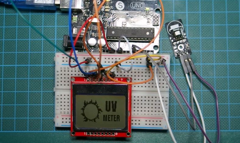
Today, we will build a UV meter using the Arduino and the ultraviolet sensor (UVM30A) with a Nokia 5110 LCD display as the display for the meter. The Nokia 5110 is used to display the UV index which is an international standard unit for the intensity of ultraviolet rays from the sun being experienced in a particular place and at a particular time.
The Purpose of measuring the UV index in a particular place and at a particular time is to prevent people from the dangers caused by high UV index rays as it could lead to things like sunburn etc. It is also measured to guide people, so they can take adequate protective measures, like the use of sunscreens, sunglasses, hats etc on a day out. A UV Protection chart which tries to match the UV index with the adequate protective devices is shown below.
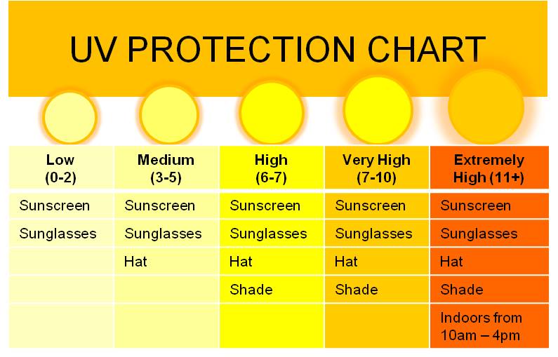
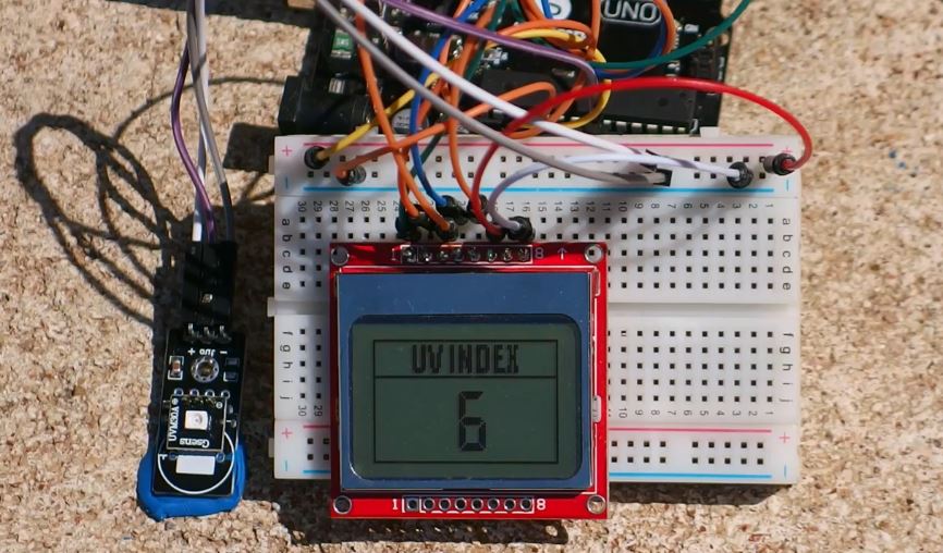
It can be seen from the chart that when UV level is extremely high it is advised to stay indoors, the reason for this is, the UV index indoors is mostly zero. This means that when testing the device we are about to build, you should take it outside as shown in the image below, as the value won’t change if you test indoors.
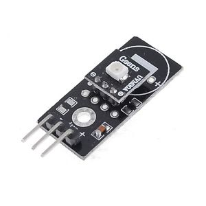
The UVM30A UV sensor which we will use for this tutorial is a low-cost analog sensor with an almost linear output. This means the output of the sensor increases or decreases with a proportional increase or decrease in UV radiation respectively. A graph of the sensor’s output (in mV) against the UV index, culled from the sensor’s datasheet to describe its linearity is shown below.
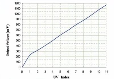
It is a simple three pin sensor consisting of the VCC, GND and the analog signal output.
With that said, let get down to business.
Required Components
The following components will be needed to build this project.
As usual, the exact components used for this tutorial can be bought by following the link attached to each of them.
Schematics
With all the components at the ready, let’s wire it up according to the schematics below;
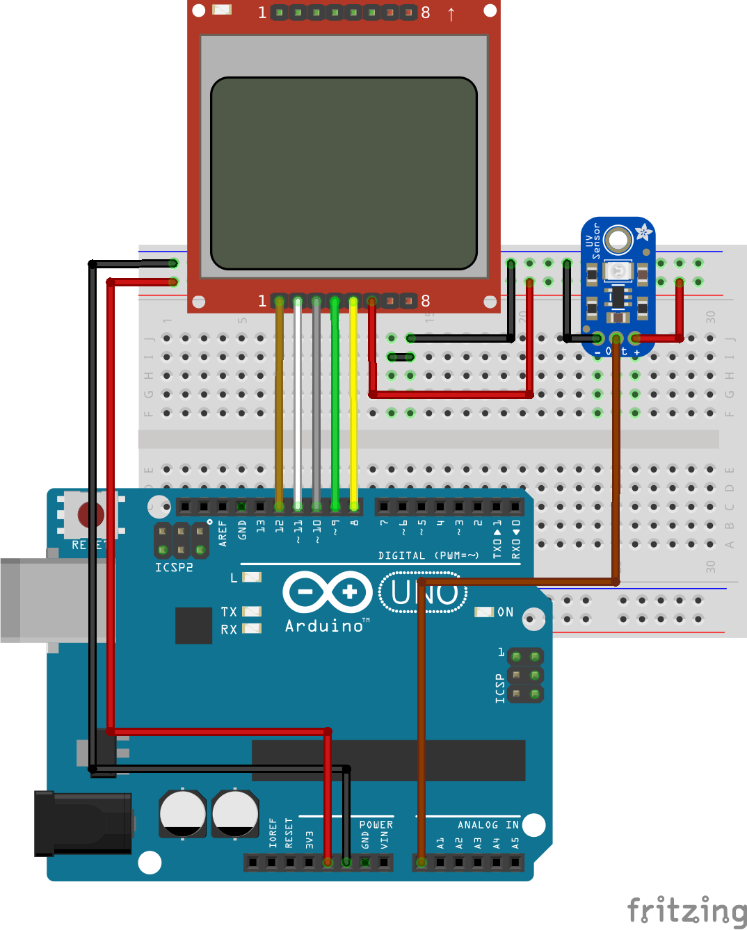
Connecting the N0kia 5110 LCD to the Arduino is an art that we have perfected over several tutorials, an example of which can be found here, but for the purpose of this tutorial, we will still include the pin map so you can easily connect it if following that schematic is a little bit difficult. Alongside the pin map for the LCD is the pin map for connecting the UV sensor to the Arduino.
UV Sensor to Arduino pin map
UV sensor – Arduino
GND - GND
VCC - VCC
output - A0
Nokia 5110 LCD to Arduino Pin map
LCD – Arduino
Pin 1(RST) – D12
Pin 2(CE) – D11
Pin 3(DC) – D10
Pin 4(DIN) – D9
Pin 5(CLK) – D8
Pin 6(VCC) - VCC
Pin 7(LIGHT) - GND
Pin 8(GND) - GND
Double check the connections to confirm everything is okay before proceeding to the code.
Code
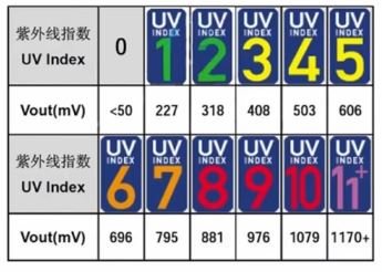
The code for this project is fairly simple, we are using only one library which is the Nokia 5110 LCD library to communicate with the LCD. The library can be downloaded from this link. The basic operation of the code is to read the analog pin 0 (A0) to which our sensor’s output is connected and convert it into mV so we can compare with the values in the UV index table and calculate the UV Index at that particular place and time. After the calculation and the UV index determination, the index is displayed to the user via the Nokia 5110 LCD. The UV index table for comparison is shown in the image below.
As usual, we will break the code into small chunks and explain before giving the full code. The code is also attached in the zip file available at the download section, located at the end of this tutorial.
To jump in, the first thing we do in the code is import the Nokia 5110 LCD library which is needed for the display.
//////////////////////////////////////////////
  //            Arduino UV Meter              //
 //            with NOKIA 5110 LCD           //
//           http://www.educ8s.tv           //
/////////////////////////////////////////////

#include <LCD5110_Graph.h>
After importing the library and making some comments on what the project is all about, we move to declare other variables and constants which will be used in the code.
LCD5110 lcd(8,9,10,12,11);
extern unsigned char BigNumbers[];
extern uint8_t splash[];
extern uint8_t ui[];

String UV = "0";
With that done, we move to the setup function. The first thing we do is initialize the LCD, then we set the fonts for the display, clear the screen with lcd.clrScr(), after which we draw the splash bitmap. The process of creating the splash bitmap and inserting it into your Arduino code was covered in details in one of our previous tutorials which can be found here.
void setup() {

 lcd.InitLCD();
 lcd.setFont(BigNumbers);
 lcd.clrScr();
 lcd.drawBitmap(0, 0, splash, 84, 48);
After the drawBitmap command, we update the LCD to reflect changes and we delay for 3000ms to ensure the splash stay long enough on the screen to be seen.
 lcd.update();
 delay(3000);

}
With the setup done, we move into the loop() function.
Here we call the readSensor function, which reads the value from the UV sensor, converts it into mV and compares it with the Index table to get the UV index match for the mV value that was read in.
void loop() {

 int stringLength = 0;

 UV = readSensor();
Next, we clear the screen and draw the UI into which the index will be inserted.
lcd.clrScr();
lcd.drawBitmap(0, 0, ui, 84, 48);
With the UI drawn, we then calculate the length of the index and it is displayed using the printUV function after which the LCD update command is called.
stringLength = UV.length();
 printUV(stringLength);
 lcd.update();
 delay(150);
}
The full code for the project is attached below.
  //////////////////////////////////////////////
  //            Arduino UV Meter              //
 //            with NOKIA 5110 LCD           //
//           http://www.educ8s.tv           //
/////////////////////////////////////////////

#include <LCD5110_Graph.h>

LCD5110 lcd(8,9,10,12,11);
extern unsigned char BigNumbers[];
extern uint8_t splash[];
extern uint8_t ui[];

String UV = "0";

void setup() {

 lcd.InitLCD();
 lcd.setFont(BigNumbers);
 lcd.clrScr();
 lcd.drawBitmap(0, 0, splash, 84, 48);
 lcd.update();
 delay(3000);

}

void loop() {

 int stringLength = 0;

 UV = readSensor();
 lcd.clrScr();
 lcd.drawBitmap(0, 0, ui, 84, 48);

 stringLength = UV.length();
 printUV(stringLength);
 lcd.update();
 delay(150);
}

void printUV(int length)
{
  switch(length)
  {
    case 1:  lcd.print(UV,38,19); break;
    case 2:  lcd.print(UV,24,19); break;
    default:  lcd.print(UV,0,19); break;
  }
}

String readSensor()
{
  String UVIndex = "0";
  int sensorValue = 0;

  sensorValue = analogRead(0);                        //connect UV sensor to Analog 0
  int voltage = (sensorValue * (5.0 / 1023.0))*1000;  //Voltage in miliVolts

  if(voltage<50)
  {
    UVIndex = "0";
  }else if (voltage>50 && voltage<=227)
  {
    UVIndex = "0";
  }else if (voltage>227 && voltage<=318)
  {
    UVIndex = "1";
  }
  else if (voltage>318 && voltage<=408)
  {
    UVIndex = "2";
  }else if (voltage>408 && voltage<=503)
  {
    UVIndex = "3";
  }
  else if (voltage>503 && voltage<=606)
  {
    UVIndex = "4";
  }else if (voltage>606 && voltage<=696)
  {
    UVIndex = "5";
  }else if (voltage>696 && voltage<=795)
  {
    UVIndex = "6";
  }else if (voltage>795 && voltage<=881)
  {
    UVIndex = "7";
  }
  else if (voltage>881 && voltage<=976)
  {
    UVIndex = "8";
  }
  else if (voltage>976 && voltage<=1079)
  {
    UVIndex = "9";
  }
  else if (voltage>1079 && voltage<=1170)
  {
    UVIndex = "10";
  }else if (voltage>1170)
  {
    UVIndex = "11";
  }
  return UVIndex;
}
Demo
Connect the Arduino board to your computer, launch the IDE and paste the code into it. Don’t forget to add the UI and the Splash files to the Arduino sketch folder for the code before uploading as this may bring up errors. The splash and UI files are part of the files in the zip file under the downloads section.
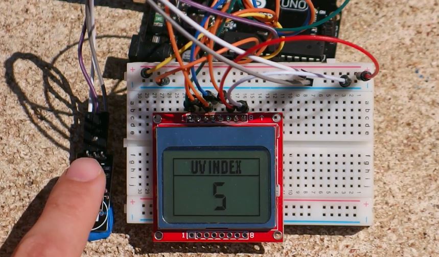
Upload the code to your board and take it outside to measure the UV intensity in your area. It was a very sunny day in Greece at the time this tutorial was written.
That’s it for this tutorial guys, as usual, you can drop comments and questions via the comment section.
Till next time.
The video tutorial for this project is available on youtube here.
5volt seems a bit much for the nokia display
Does anyone know which UV ray this sensor responds to? There are UV-A UV-B and UV-C rays. Each more dangerous than the previous. Sensors are rated by what wave lengths they detect. Ernest Hansen
It comes with UMV-30A which has as specs Response wavelength: 200nm-370nm, which is UV-A, UV-B and UV-C.
Hello. I am very new to arduino and this is my very first project. These directions are very confusing, could someone give me some guidance?
With the GUVA S12SD which must be more sensitive, the values of the example are wrong