OLED display audio VU meter – AVR/Arduino project
Today we are going to build one of the most important tools in sound mixing; A audio VU (volume unit) meter based on an Arduino/AVR microcontroller. This project serves to demonstrate how the knowledge of electronics can be applied to build solutions for any part of your day to day life.
Today we are going to build one of the most important tools in sound mixing; A audio VU (volume unit) meter based on an Arduino/AVR microcontroller. This project serves to demonstrate how the knowledge of electronics can be applied to build solutions for any part of your day to day life.
A volume unit (VU) meter or standard volume indicator (SVI) as it’s sometimes called, is a device which displays the audio signal level of an audio signal. It is essentially a basic voltmeter (fitted with transducers to convert sound to voltage) that takes a simple average of the signal and displays it with an attack and release time of around 300 ms. It was originally designed as a kind of loudness meter, rather than as a peak meter, but it is generally used in audio recording to help make sure you’re recording at appropriate levels.
Today’s version of the project is based on a project started by Adam Ples on Github and it uses AVR ATMega88/168/328 (and ATMega48 if possible) which makes it compatible with Arduino boards like the Uno, Nano and Due. For the display, the project was designed to be compatible with small (and cheap) monochrome OLED displays based on the SSD1306 or SH1106 driver.
The goal of this version of VU meter include:
- To achieve a 2-channel operation,
- Accuracy to be as close to real VU-meter specification as possible,
- high FPS, 60+ — no visible jumping of the needle, as is common in other designs.
How it Works
A simple block diagram shows how the project works:
Due to the attention to detail, and the desire to ensure it comes as close as possible to the standard of commercial VU meters, the project comprises of a slightly complex analog front end. More complex than most of the other VU based tutorials you may find on the internet but totally worth it if quality and accuracy is a goal for you.
The analog front end takes the audio signal and passes it through a rectifier block after which the signal is passed through the ballistics block which is configured to meet the very specific ballistic characteristics of VU meters. The signal is then fed into the ADC of a microcontroller which then transforms it into data to be displayed on the OLED.
Required Components/BOM
Due to the complexity of the design, replicating it on a breadboard will be difficult for the most hobbyists as such the project will be built on a PCB and the components used were optimized for that purpose. For example rather than use through-hole components, SMD Components were used. A BOM will be made available under the download section but here is a detailed list of the components used;
| Part Name | Technology | Package | Value | Add. Params | Quantity |
| Resistors | Thin film | 0805 | 10k | 1% | 15 |
| Thick film | 0805 | 220R | 2 | ||
| 1k | 2 | ||||
| 22k | 2 | ||||
| 47k | 2 | ||||
| 82k | 2 | ||||
| 220k | 10 | ||||
| Trimmer | 3296W | 10k | 2 | ||
| Capacitors | Ceramic | 0805 | 22pF | 2 | |
| 33pF | 2 | ||||
| 220pF | 4 | ||||
| 47nF | 2 | ||||
| 100nF | 10 | ||||
| 220nF | 2 | ||||
| 330nF | 4 | ||||
| 470nF | 2 | ||||
| 1uF | 2 | ||||
| 10uF | 1 | ||||
| Tantalum | 1210 | 10uF | 16V | 1 | |
| 100uF | 6.3V | 2 | |||
| Diodes | SOD80 | 1N4148 | 2 | ||
| BAT85 | 2 | ||||
| SOT23 | BAS70-04 | 2 | |||
| Transistors | SOT23 | BSS138 | 2 | ||
| Integrated Circuits | linear regulator | SOT223 | 1117-5.0 | 1 | |
| SOT23 | MCP1700*33 | 1 | |||
| SOT23 | MCP1525 | 1 | |||
| Op-amp | SO14 | MCP604 | 1 | ||
| MCP6004 | 2 | ||||
| Microcontroller | TQFP32 | ATmega88P | 1 | ||
| Others | Crystal resonator | HC49/S | 20MHz | 1 | |
| Choke | 1210 | 10uH | 1 | ||
| Pin headers | 1×2 | 1 | |||
| 1×3 | 1 | ||||
| 2×3 | 1 | ||||
| 2×4 | 1 |
These components are readily available and can be bought from most electronic component stores.
Schematics
To make the project easy to use, the VU meter was designed to come either as a standalone module or as a shield, pin-compatible, and to be plugged on boards like the Arduino Uno. As mentioned earlier the complexity of the project makes it a tedious task to implement on breadboards, as such, both the schematics and the PCB design will be shared under this section and also attached in the zip file under the download section. The Schematics and PCB were developed with Eagle, so you should be able to modify as you want.
Standalone module Schematics and PCB
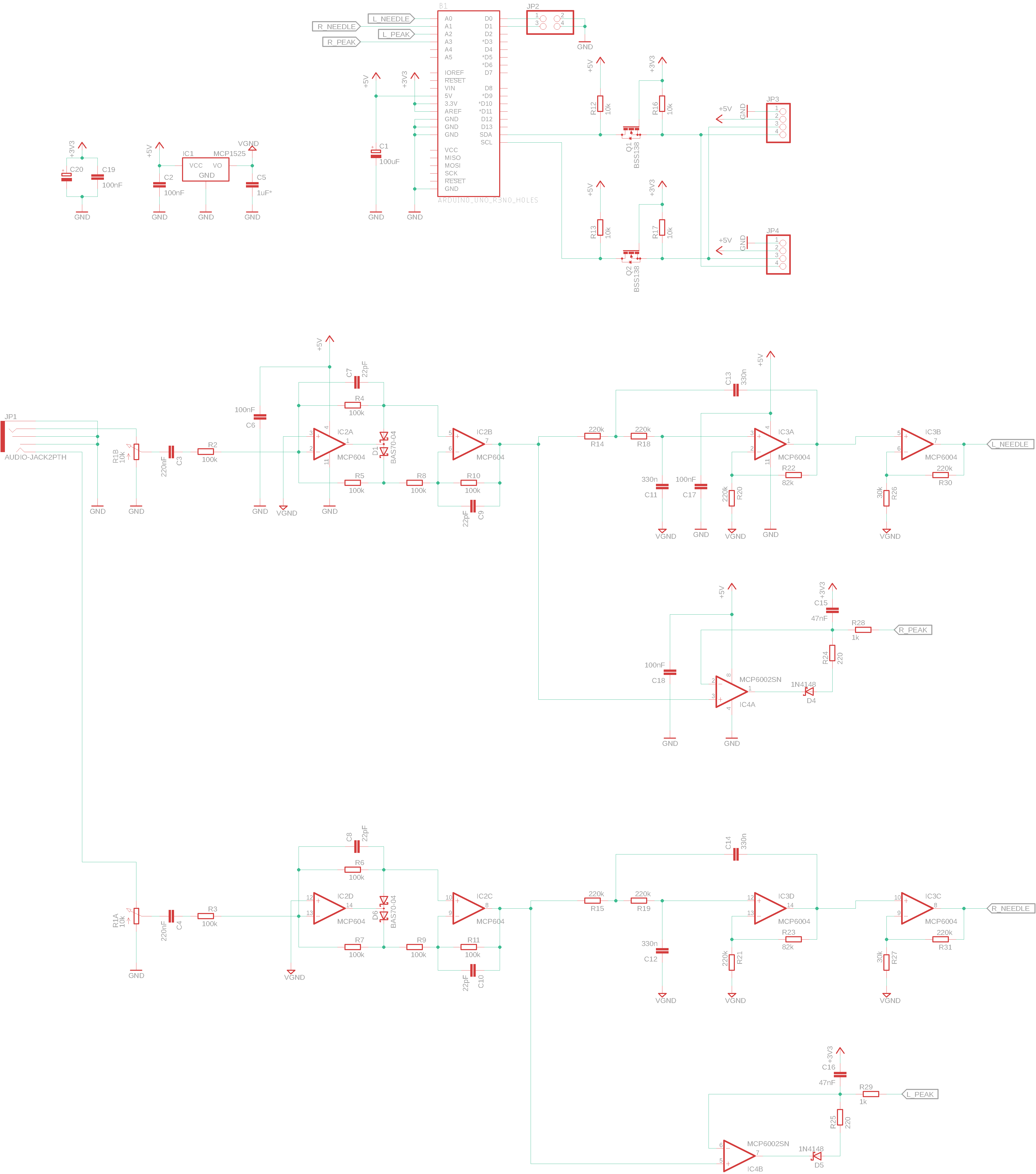
The schematics for the module is shown in the image below. The schematic is quite large, as such, you might need to zoom in to properly see how the components are connected.
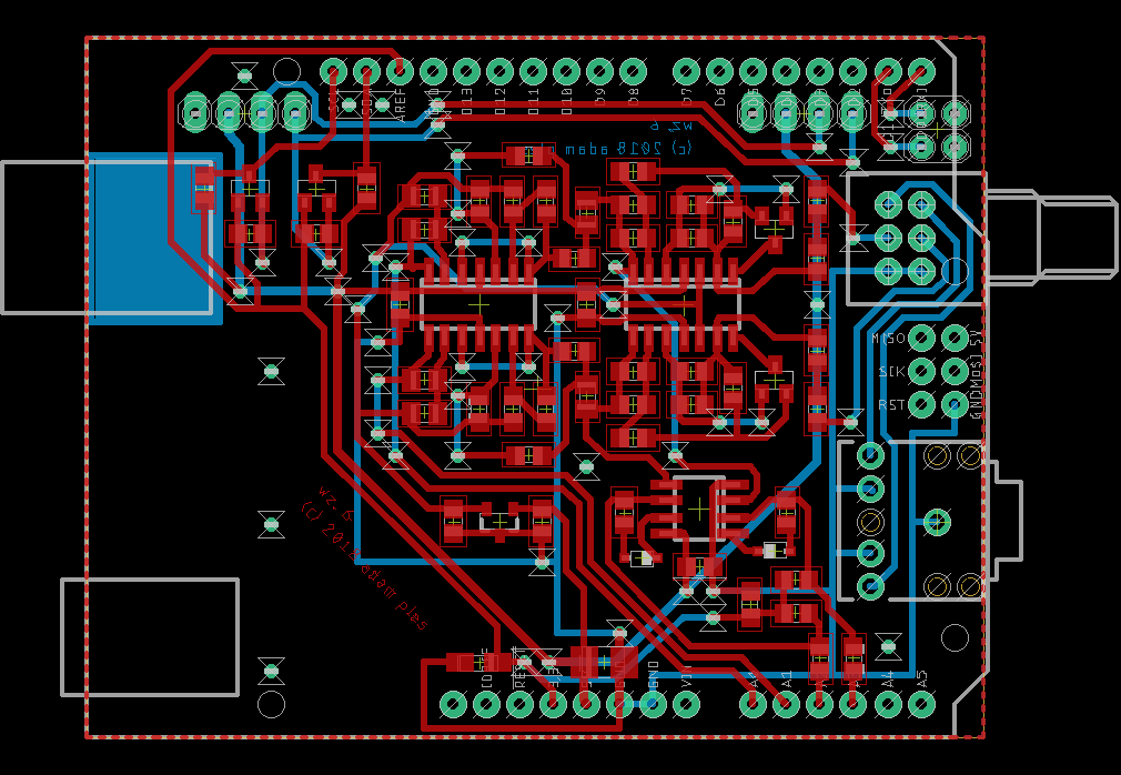
The image below represents the PCB of the VU meter after all the components have been placed. The PCB file is attached under the download section, feel free to edit and make changes in the arrangement as you desire.
VU-Meter Shield for Arduino
The VU meter shield is designed to run off the Arduino Uno and should work with other Uno Compatible board. The schematics for the shield is shown in the image below.
Transforming the schematics to PCB, we get the image below.
Software
The source code for the project is provided in the .src file under the download section. To flash your board with the code, you will have to build the .hex file from the files in the source folder and flash your board with it.
To build a hex file from the source code, you will need the following tools:
- Avr-GCC
- GNU make
- Python 2.7 or 3
For windows users, you can use this distribution of GCC and make: http://blog.zakkemble.co.uk/avr-gcc-builds/. Before compilation, ensure you take a look at all the files in the src folder as there might be one or two that may require modification to tailor the project to your specific needs. For instance, the Config.h file under the source folder (src/config.h) houses configurations for the project and you may need to modify it and do things like changing the OLED controller type to match your own OLED. You may also need to modify the content of the Makefile to set the microcontroller you are using and the oscillator frequency (F_CPU).
To create the hex file type
With your Avr-GCC and other tools installed, open a terminal (or command prompt) on your PC, change directory to the folder containing all the project files including the “src” using the “cd command” then run the make command to create the hex file;
$ make all
This will create a main.hex file under the build folder. This hex file can then be used to flash your device.
While flashing the module version of the VU meter with the hex file may be quite easily achieved courtesy of tools like the Atmel Studio, the case is quite different for the shield, as flashing an Arduino board with a hex file gets a bit tricky since the feature is not a part of the Arduino IDE.
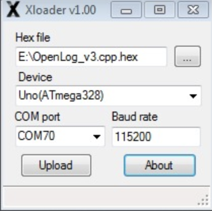
To solve this and flash the Arduino board with the .hex file, we will use a tool called xLoader. The xLoader is a simple tool that allows you easily flash your Arduino board with hex files. It has a simple user interface that allows you to select the file, set the COM port and BAUD RATE, and just hit upload. The only downside to this tool is it’s only available for Windows PCs.
Download and install the xLoader from the attached link, then connect your Arduino board to the computer, select the .hex file we generated as shown below, set the baud rate and comport to match that of your Arduino, and hit upload.
The same process can be used to flash the Module version of the VU meter with the hex file.
Demo
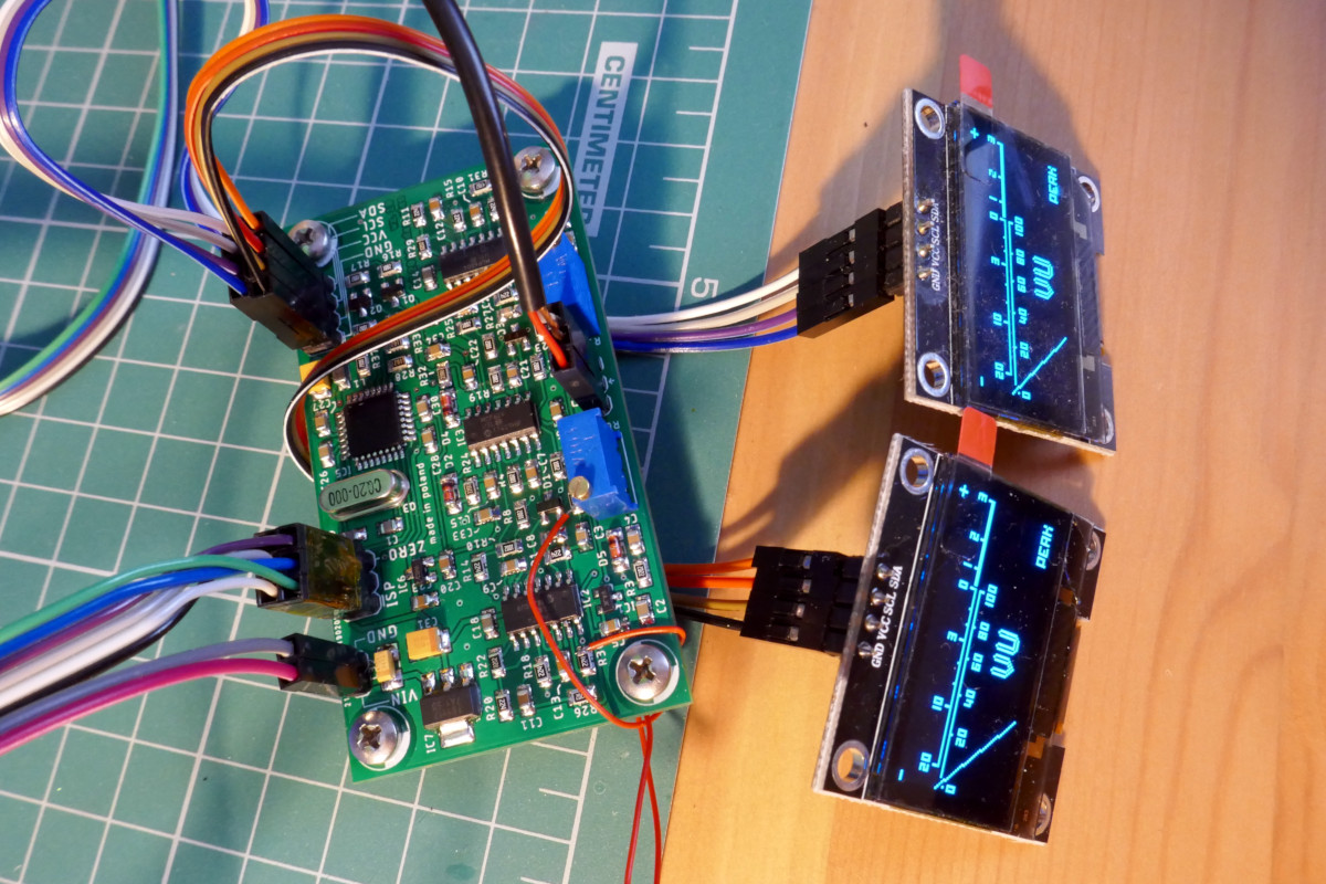
With the code uploaded, plug in an audio source into one or both audio channels. You should see the needle on the VU meter deflect in tune with the volume property of the audio source.
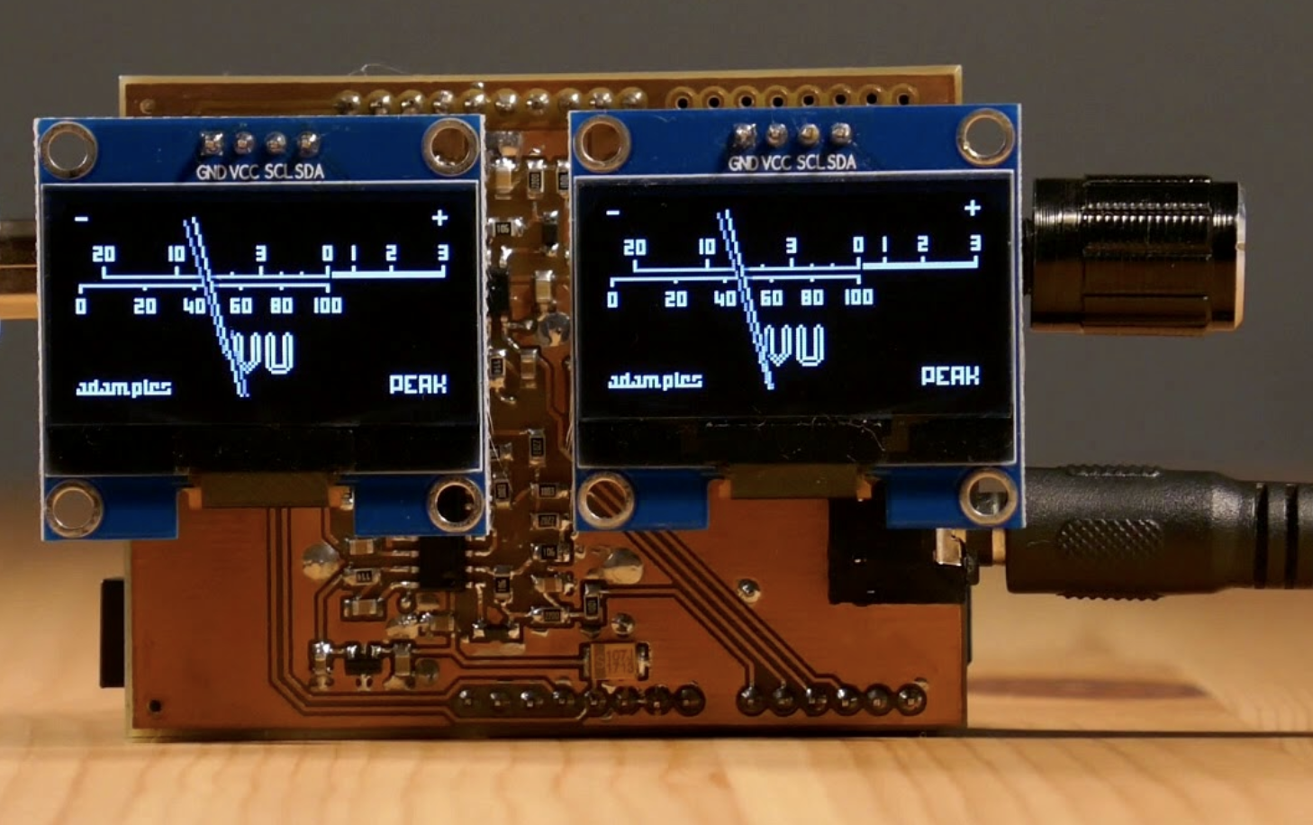
The same thing for the module. After flashing it with the .hex file, connect some sound to it, you should see the needle move accordingly.
That’s it for this tutorial. As mentioned above one of the goals of this tutorial was to show you how tools you use every day can be replicated using electronic components that make it way cheaper and useful.
What other tools will you be making? Feel free to reach out to me via the comment section with questions and experiences that you feel could benefit everyone.
You can watch the video version of the demo by Adam Ples.