Portable Fine Dust PM10 Analyzer with Large OLED Digits
In one of our previous articles, we built a DIY air quality monitor which was based on measuring the amount of Hydrocarbon concentration in the air using the BME680 VOC Whisker. While things work quite well using that method, there are several other parameters and air constituents which also have the same devastating effect and may be present in the air, but not detected by the sensor used in our previous project.
In one of our previous articles, we built a DIY air quality monitor which was based on measuring the amount of Hydrocarbon concentration in the air using the BME680 VOC Whisker. While things work quite well using that method, there are several other parameters and air constituents which also have the same devastating effect and may be present in the air, but not detected by the sensor used in our previous project. One of such easy to overlook, constituents of air is Particulate Matter, and for today’s tutorial, we will build a device to measure its concentration in air.
Particulate matter is the sum of all solid and liquid particles (many of which are hazardous) suspended in the air. It is a complex mixture of organic and inorganic particles, such as dust, pollen, soot, smoke, and liquid droplets. These particles are created mostly when fuel is burnt and when the dust is carried by the wind. They vary greatly in origin, composition, and size which is the most popular way of categorizing them with the PM10 and PM2.5 classification.
For today’s tutorial, we will build a device capable of determining the amount of particulate matter in the air around it. The device will be capable of monitoring PM10 and PM2.5 grade particles and display results on an OLED Display. The value displayed can be used in advising the users to wear a face mask or adopt other ways to protect themselves from polluted air.
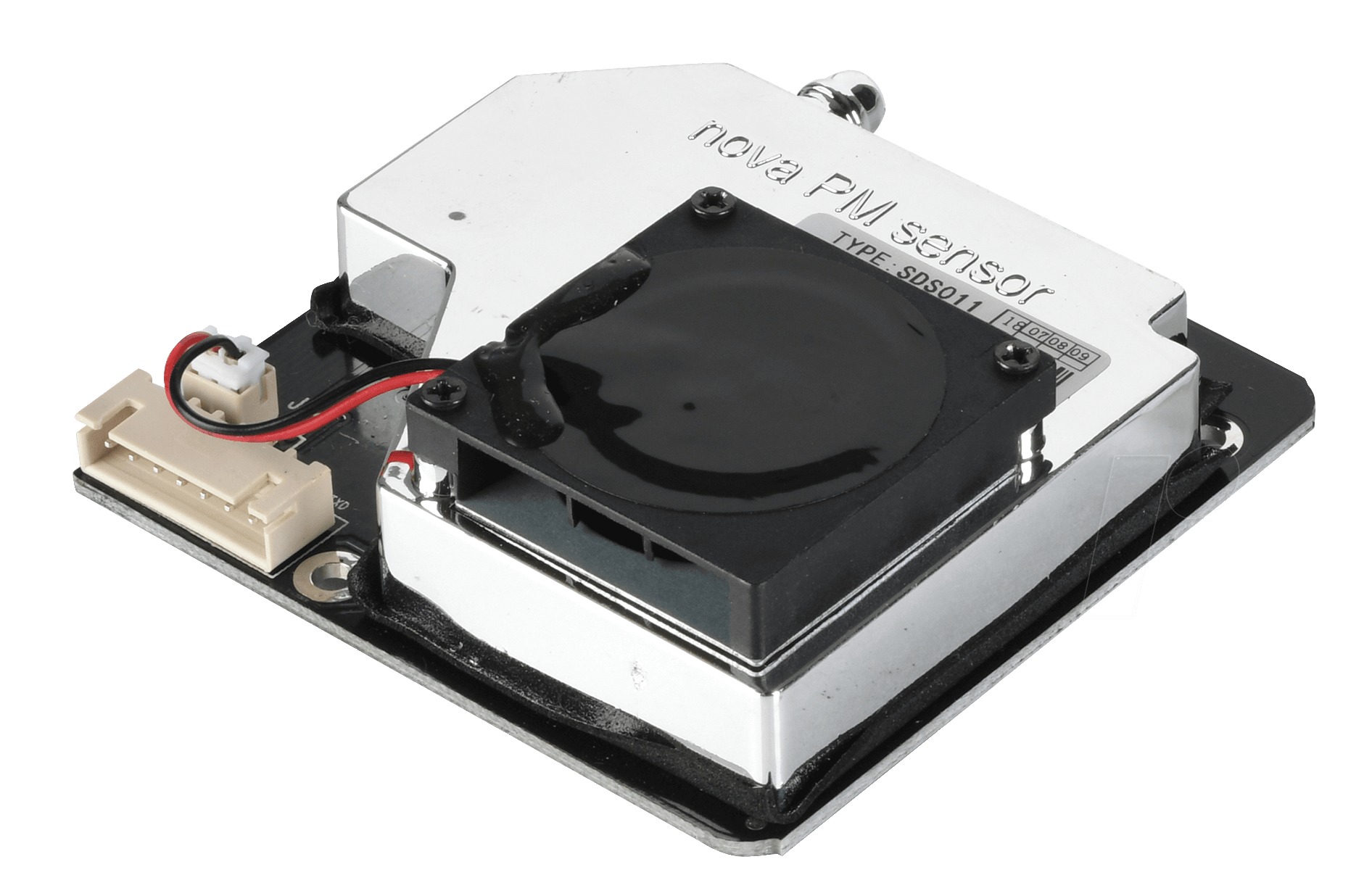
While there are several projects on the internet measuring particulate matter, today’s project will be chronicling the efforts of user “plouc68000″ due to the low power features implemented which enabled the use of batteries in powering the device. The PM10 Dust Analyzer built by “plouc68000” is based on the Nova PM sensor: SDS011 combined with an I2C OLED on which the measurements are displayed in big digits so it is clear and easy to read.
At the end of this tutorial, you would know how to work with the Nova PM Sensor, the I2C OLED Display and also build your own air quality monitor.
Required Components
The following components are required to build this project:
- Arduino Uno
- Nova PM Sensor SDS011
- Graphic OLED 128×64
- Jumper wires
- Breadboard
The exact components used for the tutorial can be bought from the links attached to them.
Schematics
The schematics for this project is quite straightforward. The OLED display is connected to the Uno via the I2C pins (A4 and A5) while the output pin of the NOVA PM sensor is connected to a digital pin on the Uno. For the sake of this project, it was connected to pin D2 on the UNO.
The schematics showing how the components are connected is provided in the image below.
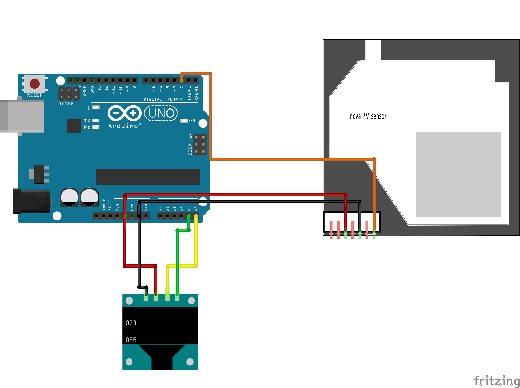
To make the connection even easier to follow, a pin to pin map showing how the components connect to the Arduino is provided below:
Arduino – OLED
5V - VCC
A4 - SDA
A5 - SCL
GND - GND
Arduino – SDS011
GND - GND
5V - VCC
D2 - Dout
Code
As mentioned during the introduction, our goal for today’s project is simple and the code, straightforward. We analyze the Particulate Matter content of the air around us using the SDS011 PM sensor and display the value obtained on the OLED display.
To achieve this, we will develop the code using the Arduino IDE. This means the code will be in the familiar Arduino version of the C/C++ programming language.
To reduce the work involved in developing the code for the project, we will use two major libraries including; The U8glib and the Software Serial library. The Software Serial library is used to interact with the SDS011 sensor while the U8glib library is used to interact with the OLED display. While the Software Serial library comes preinstalled on the IDE, the U8glib can be downloaded and manually installed via the attached link.
As usual, I will do a quick explanation of some snippets/parts of the code which I feel may be slightly difficult to follow. We start the sketch, like always, by including all the libraries that we will be using. They are essentially the same as the ones mentioned above.
#include "SoftwareSerial.h"
#include "U8glib.h"
Next, we create an object of both libraries along with some global variables that will hold readings for PM10 and PM2.5.
SoftwareSerial mySerial(2, 3); // RX, TX for SDS011 sensor ( to keep Serial monitor available )
U8GLIB_SSD1306_128X64 u8g(U8G_I2C_OPT_NONE);  // for 1306 type OLED, I2C / TWI

// Global Variables
static unsigned char buf[7], buffSDS[25];
unsigned int PM2_5,PM10=0;
Next, we create two(2) functions/Subroutines. The first one is the void draw() function which is used in displaying all kinds of data on the OLED, while the second is the Val_to_string() function which is used to convert “int” into buf[] to BCD string so it can be displayed on the OLED.
// Sub Routines

// Update OLED Display
void draw(void) {
  /* for the line with PM2.5 value */
  if ( PM2_5>999 ) PM2_5=999 ;// overflow is 999
  val_to_string(PM2_5);

  u8g.setFont(u8g_font_fub30);// Large font
  u8g.drawStr( 0, 31, buf); //
  u8g.setFont(u8g_font_unifont);
  u8g.drawStr( 75, 10, "PM2.5");
  buf[0]='µ';
  buf[1] = '\0';
  u8g.drawStr( 75, 10+2+10, buf);
  u8g.drawStr( 82, 10+2+10, "g/m3");

  // for the line with PM10 value
  if ( PM10>999 ) PM10=999 ;// overflow
  val_to_string(PM10);

  u8g.setFont(u8g_font_fub30);// Large font
  u8g.drawStr( 0, 65, buf); //
  u8g.setFont(u8g_font_unifont);
  u8g.drawStr( 75, 34+10, "PM10");
  buf[0]='µ';
  buf[1] = '\0';
  u8g.drawStr( 75, 34+10+2+10, buf);
  u8g.drawStr( 82, 34+10+2+10, "g/m3");
}


/* convert int into buf[] to BCD string to be OLED printed */
void val_to_string(int val){

  int deca[5];
  deca[4]=10000;
  deca[3]=1000;
  deca[2]=100;
  deca[1]=10;
  deca[0]=1;

  char digit[10];
  digit[0]='0';
  digit[1]='1';
  digit[2]='2';
  digit[3]='3';
  digit[4]='4';
  digit[5]='5';
  digit[6]='6';
  digit[7]='7';
  digit[8]='8';
  digit[9]='9';

  buf[0]='0';
  buf[1]='0';
  buf[2]='0';
  buf[3]='\0'; // string terminator, only 3 digits needed
  buf[4]='0';
  buf[5] = '\0'; // not used

  for ( int8_t i=2; i>=0 ; i=i-1 )
  {
    byte d=0;
    while (( val-deca[i]) >= 0)
    { val=val-deca[i];
      buf[2-i]=digit[++d];
    }
  }
}
With the functions in place, we now proceed to the void Setup() function. We start the function by setting the color index to a single color (monochrome) to aid the clarity with which the data is displayed.
void setup() {
// init 1306 I2C OLED
 u8g.setColorIndex(1); // monochrome
Next, we, initialize serial communication between the Uno and the SDS011, setting its timeout and stop bytes.
// Read SDS011 on Serial
mySerial.begin(9600);  //
mySerial.setTimeout(200);
mySerial.readBytesUntil(0xAB,buffSDS,20); // read serial until 0xAB Char received
We wrap up the function by initializing the hardware serial communication to enable us to use the serial monitor for debugging purposes.
// Serial Monitor
Serial.begin(115200);
}
With that done, we move to the void loop function.
We start the loop function displaying the first page which is meant to serve as a home screen.
void loop() {
 // LCD Update
  u8g.firstPage();
  do {
    draw();
  } while( u8g.nextPage() );
Next, we read the SDS011 and print the data read on the serial monitor.
// Read SDS011
mySerial.readBytesUntil(0xAB,buffSDS,20);

// Serial monitor, print the HEX bytes received in buffSDS
//Serial.write(buffSDS,10);
for ( int8_t i=0; i<10 ; i=i+1 )
  {
  Serial.print( buffSDS[i],HEX);
  Serial.print(" ");
  }
Serial.println("");
The level of PM 2.5 present in the air is then obtained and the same is done for the PM10. The values obtained are then displayed on the serial monitor and the OLED. A small delay is added at the end of the code to ensure stability in readings.
PM2_5 = ((buffSDS[3]*256)+buffSDS[2])/10; // extract PM2.5 value
Serial.print("PM2.5: ");
Serial.println(PM2_5);

PM10 = ((buffSDS[5]*256)+buffSDS[4])/10; // extract PM10 value
Serial.print("PM10: ");
Serial.println(PM10);

delay(500);
}
With that done. we are ready to upload the code and test things out.
The complete code for the project is available below and also attached under the download section.
// UNO version of PM10 Analyser
#include "SoftwareSerial.h"
#include "U8glib.h"

SoftwareSerial mySerial(2, 3); // RX, TX for SDS011 sensor ( to keep Serial monitor available )
U8GLIB_SSD1306_128X64 u8g(U8G_I2C_OPT_NONE);  // for 1306 type OLED, I2C / TWI

// Global Variables
static unsigned char buf[7], buffSDS[25];
unsigned int PM2_5,PM10=0;

// Sub Routines

// Update OLED Display
void draw(void) {
  /* for the line with PM2.5 value */
  if ( PM2_5>999 ) PM2_5=999 ;// overflow is 999
  val_to_string(PM2_5);

  u8g.setFont(u8g_font_fub30);// Large font
  u8g.drawStr( 0, 31, buf); //
  u8g.setFont(u8g_font_unifont);
  u8g.drawStr( 75, 10, "PM2.5");
  buf[0]='µ';
  buf[1] = '\0';
  u8g.drawStr( 75, 10+2+10, buf);
  u8g.drawStr( 82, 10+2+10, "g/m3");

  // for the line with PM10 value
  if ( PM10>999 ) PM10=999 ;// overflow
  val_to_string(PM10);

  u8g.setFont(u8g_font_fub30);// Large font
  u8g.drawStr( 0, 65, buf); //
  u8g.setFont(u8g_font_unifont);
  u8g.drawStr( 75, 34+10, "PM10");
  buf[0]='µ';
  buf[1] = '\0';
  u8g.drawStr( 75, 34+10+2+10, buf);
  u8g.drawStr( 82, 34+10+2+10, "g/m3");
}


/* convert int into buf[] to BCD string to be OLED printed */
void val_to_string(int val){

  int deca[5];
  deca[4]=10000;
  deca[3]=1000;
  deca[2]=100;
  deca[1]=10;
  deca[0]=1;

  char digit[10];
  digit[0]='0';
  digit[1]='1';
  digit[2]='2';
  digit[3]='3';
  digit[4]='4';
  digit[5]='5';
  digit[6]='6';
  digit[7]='7';
  digit[8]='8';
  digit[9]='9';

  buf[0]='0';
  buf[1]='0';
  buf[2]='0';
  buf[3]='\0'; // string terminator, only 3 digits needed
  buf[4]='0';
  buf[5] = '\0'; // not used

  for ( int8_t i=2; i>=0 ; i=i-1 )
  {
    byte d=0;
    while (( val-deca[i]) >= 0)
    { val=val-deca[i];
      buf[2-i]=digit[++d];
    }
  }
}


void setup() {
  // put your setup code here, to run once:

// init 1306 I2C OLED
 u8g.setColorIndex(1); // monochrome

// Read SDS011 on Serial
mySerial.begin(9600);  //
mySerial.setTimeout(200);
mySerial.readBytesUntil(0xAB,buffSDS,20); // read serial until 0xAB Char received

// Serial Monitor
Serial.begin(115200);
}


void loop() {
 // LCD Update
  u8g.firstPage();
  do {
    draw();
  } while( u8g.nextPage() );

// Read SDS011
mySerial.readBytesUntil(0xAB,buffSDS,20);

// Serial monitor, print the HEX bytes received in buffSDS
//Serial.write(buffSDS,10);
for ( int8_t i=0; i<10 ; i=i+1 )
  {
  Serial.print( buffSDS[i],HEX);
  Serial.print(" ");
  }
Serial.println("");


PM2_5 = ((buffSDS[3]*256)+buffSDS[2])/10; // extract PM2.5 value
Serial.print("PM2.5: ");
Serial.println(PM2_5);

PM10 = ((buffSDS[5]*256)+buffSDS[4])/10; // extract PM10 value
Serial.print("PM10: ");
Serial.println(PM10);

delay(500);
}
Demo
Launch an instance of the Arduino IDE, copy the code above and paste it in the IDE. Connect your Arduino Uno or any other board you decide to use, select the appropriate board type and port, then hit the upload button.
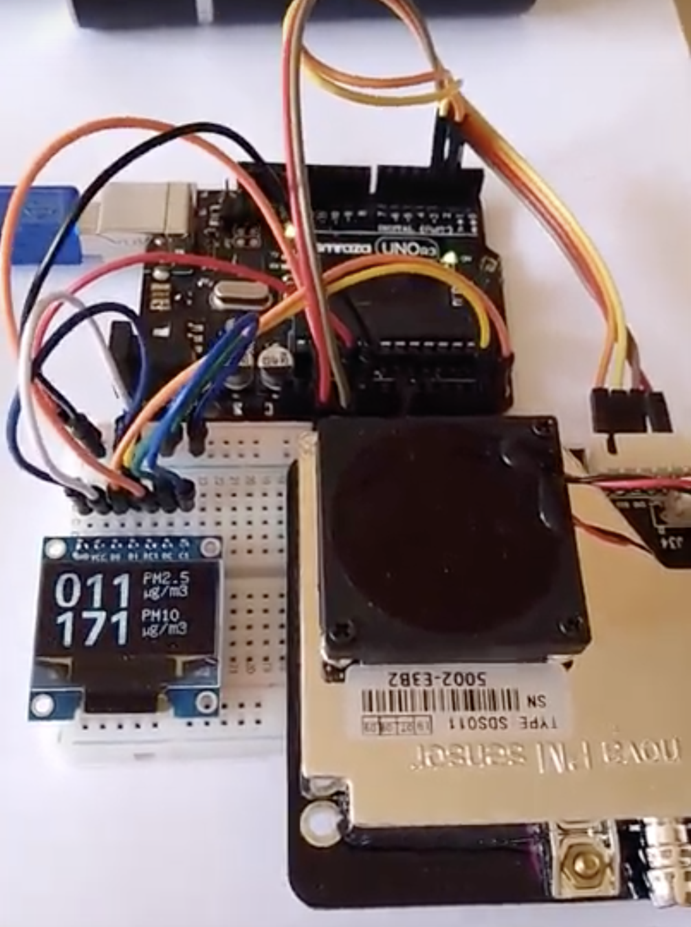
With the upload completed, you can test the project by bringing something with dust close to the device’s air intake or take the device to a dusty environment. After a few minutes, you should see the value PM10 and PM 2.5 values being displayed on the OLED display, rise in proportion to the amount of dust discovered by the device as shown in the image below.
Going Forward
An obvious, super cool, next step will be to merge this project with the last project which measures the concentration of hydrocarbons in the air. Combining these two will provide a wider and more accurate base for us to measure the air quality index. The data can also be connected to the cloud to share the data with others, transforming the project into an IoT endeavor.
That’s it for this tutorial. As usual, feel free to reach out to me via the comment section with questions as regards the project. A video of the project in action as created by plouc68000 is available on youtube.
many thank’s, it works very well! But i took one oled with 2 colors… https://www.amazon.fr/gp/product/B076PNP2VD/ref=ppx_yo_dt_b_asin_title_o05_s00?ie=UTF8&psc=1 how can i change the program to cut the two colors in half part?
I think your schematic is not accurate? I saw in your youtube video, if I am not seeing wrong, the RX pin of the dust sensor is also connected to Arduino pin 3