Under Voltage Lockout Relay – Latching Voltage Monitor
This project prevents/disconnects the load when an under-voltage condition occurs. The circuit latches the output when input sense voltage drops below the lockout threshold.
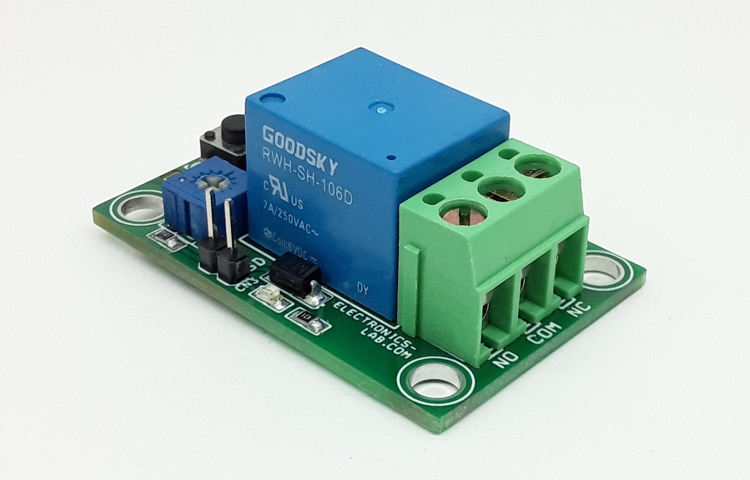
This project prevents/disconnects the load when an under-voltage condition occurs. The circuit latches the output when input sense voltage drops below the lockout threshold. Lockout threshold voltage can be adjusted using the onboard trimmer potentiometer PR1. Tactile switch SW1 is provided to reset the latch when input sense voltage is back to normal. The circuit consists of a MAX835 chip, 5V Relay, BC857 PNP transistor to drive the Relay, power LED, Relay/Output LED, and tactile switch. MAX835 chip features a level-sensitive latch, eliminating the need to add hysteresis to prevent oscillations in load-disconnect applications.
MAX835 micropower voltage monitors have a 1.204V precision bandgap reference, comparator, and latched output in a 5-pin SOT23 package. Using the latched output prevents deep discharge of batteries and disconnects the load from the power supply when Undervoltage is detected at input sense voltage. MAX835 has a push-pull output driver. Two external resistors set the trip-threshold voltage.
Operation
Connect an adjustable power supply to CN3 and apply input sense voltage in the range 3.4V to 8V, turn the PR1 trimmer potentiometer till the LED D3 is ON. Then the board is set for Undervoltage detection. For example, apply 4.90V to the CN3, rotate the PR1 so LED D3/Relay is on, the circuit is set for under-voltage detection threshold of 4.90V, now increase the input sense voltage to 5V and reset the latch using SW1.
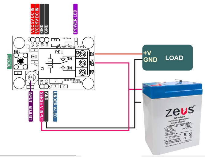
Connections
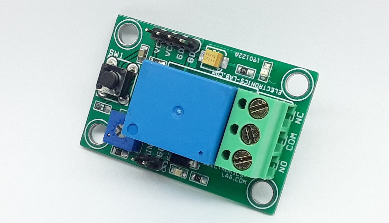
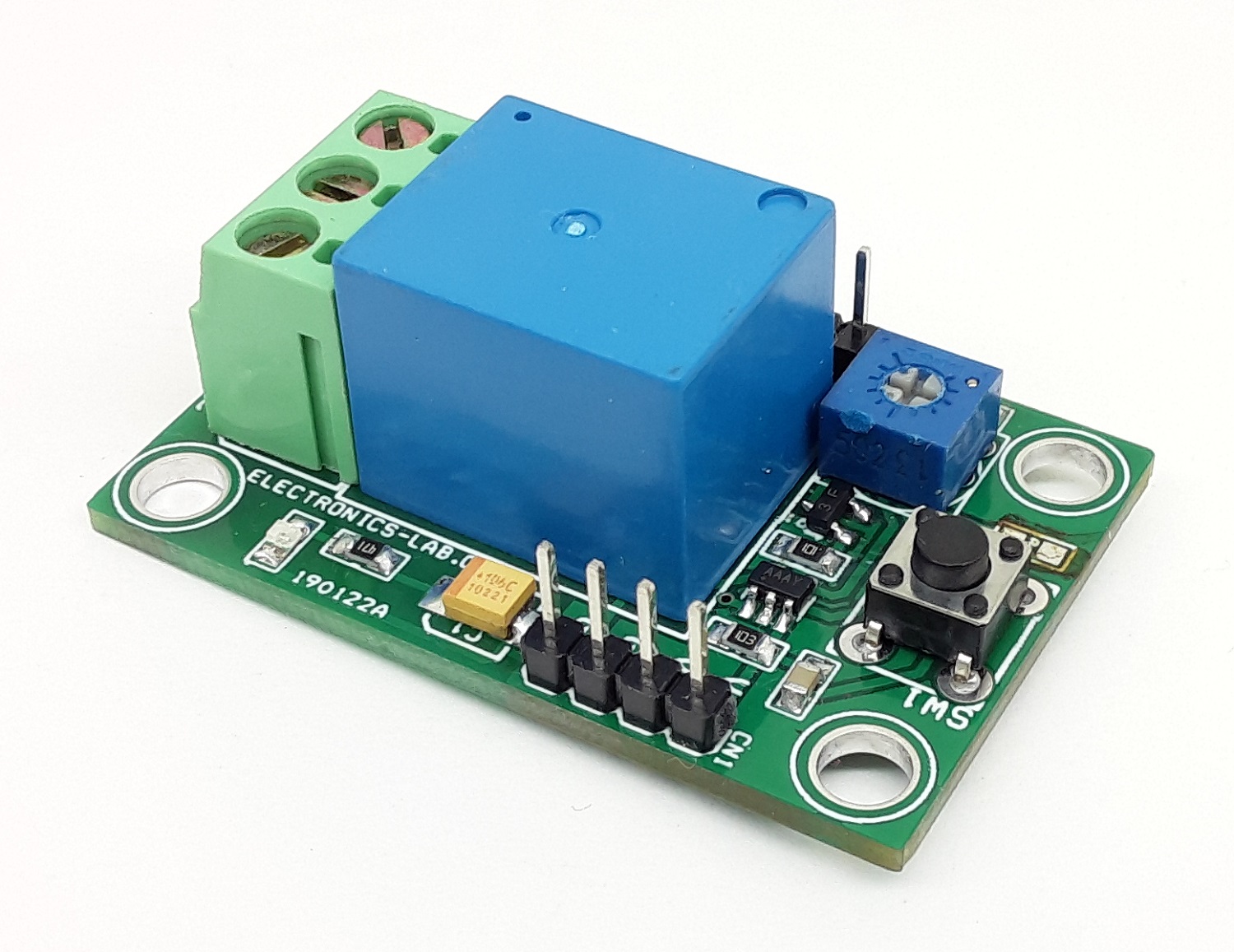
- CN1 = Pin1 VCC, Pin 2 VCC, Pin 3 GND, Pin 4 GND
- CN2= Pin 1 Sense Voltage Input, Pin 2 GND
- SW1 = Reset Switch
- D1 = Power LED
- D3 = Function LED – Relay Output
- PR1 = Trimmer Potentiometer Input Sense Voltage Adjust
- CN2 = Load Connection, Pin 1 Normally Closed, Pin 2 Common, Pin 3 Normally Open
Features
- Supply 5V DC @ 50mA when Relay is on
- Load Up to 7A, which can be increased -> Read Note 1
- Input Voltage Range 3.4V to 8V
- On Board Tact Switch for Latch Reset SW1
- Latched Output (Once Low, Stays Low Until Cleared)
- Precision +/-1.25% Voltage Threshold
- LED D3, Alert Monitor – LED is ON when output is Latched (OFF)
- LED D1, Power LED
- 4 x 3MM Mounting Holes
- PCB Dimensions 45.25 x 29.53mm
Schematic

Parts List
| NO. | QNTY. | REF. | DESC. | MANUFACTURER | SUPPLIER | PART NO |
|---|---|---|---|---|---|---|
| 1 | 1 | CN1 | 4 PIN MALE HEADER PITCH 2.54MM | WURTH | DIGIKEY | 732-5317-ND |
| 2 | 1 | CN2 | 3 PIN SCREW TERMINAL PITCH 5.08MM | PHOENIX | DIGIKEY | 277-1248-ND |
| 3 | 1 | CN3 | 2 PIN MALE HEADER PITCH 2.54MM | WURTH | DIGIKEY | 732-5315-ND |
| 4 | 1 | C1 | 10uF/16V SMD SIZE 1210 OR 1206 | YAGEO/MURATA | DIGIKEY | |
| 5 | 1 | C2 | 0.1uF/50V SMD SIZE 0805 | YAGEO/MURATA | DIGIKEY | |
| 6 | 1 | D1 | LED SMD RED | LITE ON INC | DIGIKEY | 160-1427-1-ND |
| 7 | 1 | D2 | 1N4007 SMD | DIODE | DIGIKEY | S1MBDITR-ND |
| 8 | 1 | PR1 | 5K TRIMMER POTENTIOMETER | BOURNS | DIGIKEY | 3362H-502LF-ND |
| 9 | 1 | Q1 | BC857 SMD SOT23-3 | ONSEMI | DIGIKEY | BC857CDW1T1GOSCT-ND |
| 10 | 1 | RE1 | RELAY 5V DC | CIT RELAY | DIGIKEY | 2449-J107F1CS125VDC.36-ND |
| 11 | 2 | R1,R6 | 470E 5% SMD SIZE 0805 | YAGEO/MURATA | DIGIKEY | |
| 12 | 1 | R2 | 10K 5% SMD SIZE 0805 | YAGEO/MURATA | DIGIKEY | |
| 13 | 1 | R3 | 100E 5% SMD SIZE 0805 | YAGEO/MURATA | DIGIKEY | |
| 14 | 1 | R4 | DNP | |||
| 15 | 1 | R5 | 9.01K 1% SMD SIZE 0805 | YAGEO/MURATA | DIGIKEY | |
| 16 | 1 | SW1 | 4 PIN TACTILE SWITCH | NKK SWITCH | DIGIKEY | HP0215AFKP2-ND |
| 17 | 1 | U1 | MAX835 SOT223 5 PIN | MAXIM | DIGIKEY | MAX835EUK+TCT-ND |
| 18 | 1 | D3 | LED SMD GREEN SMD SIZE 0805 | DIALIGHT | DIGIKEY | 350-2044-1-ND |
Connections
Gerber View
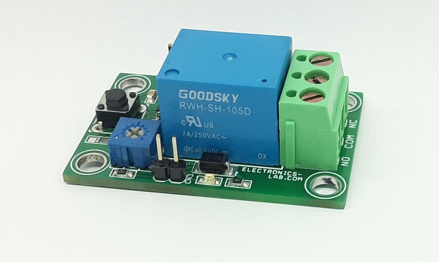
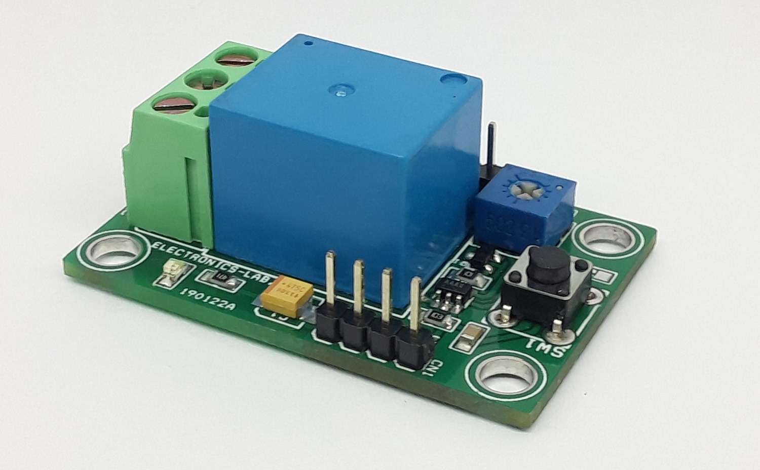
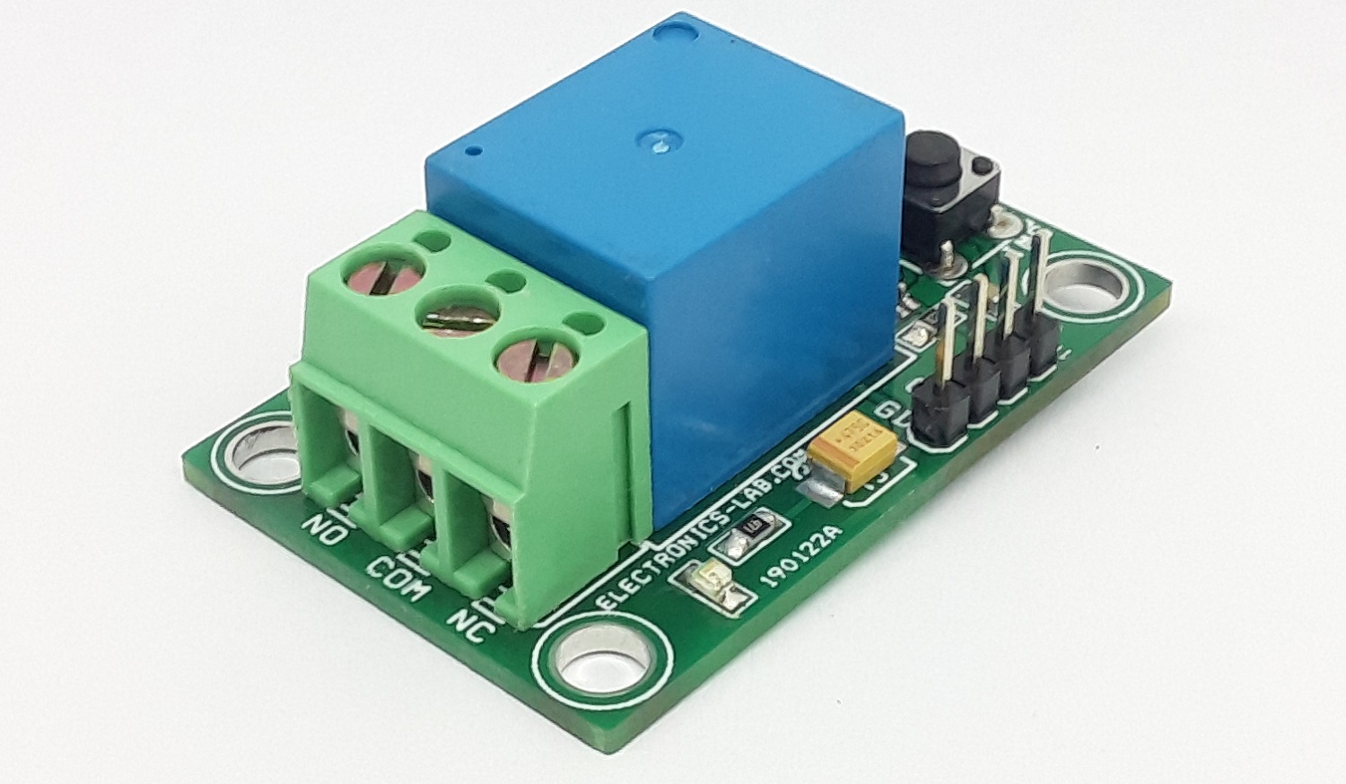
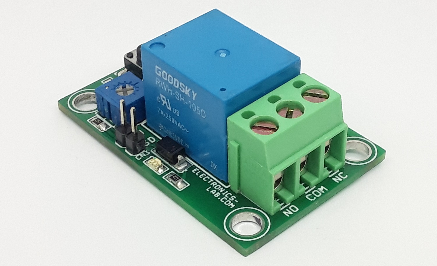
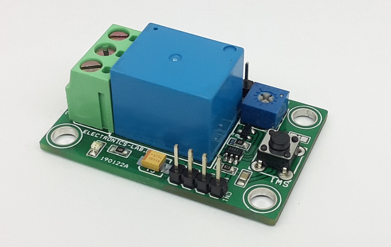
Photos