YADL: Yet Another Data Logger using TI SensorTag
Over time we have built quite a number of data logger projects, but the emergence of more modern development boards, sensors and platforms mean there is an opportunity to add several new features to data-logging devices. For today's tutorial, we are going to build a datalogger based on one of Arduino's recent boards; the Nano 33 Sense IoT board.
Over time we have built quite a number of data logger projects, but the emergence of more modern development boards, sensors and platforms mean there is an opportunity to add several new features to data-logging devices. For today’s tutorial, we are going to build a datalogger based on one of Arduino’s recent boards; the Nano 33 Sense IoT board.
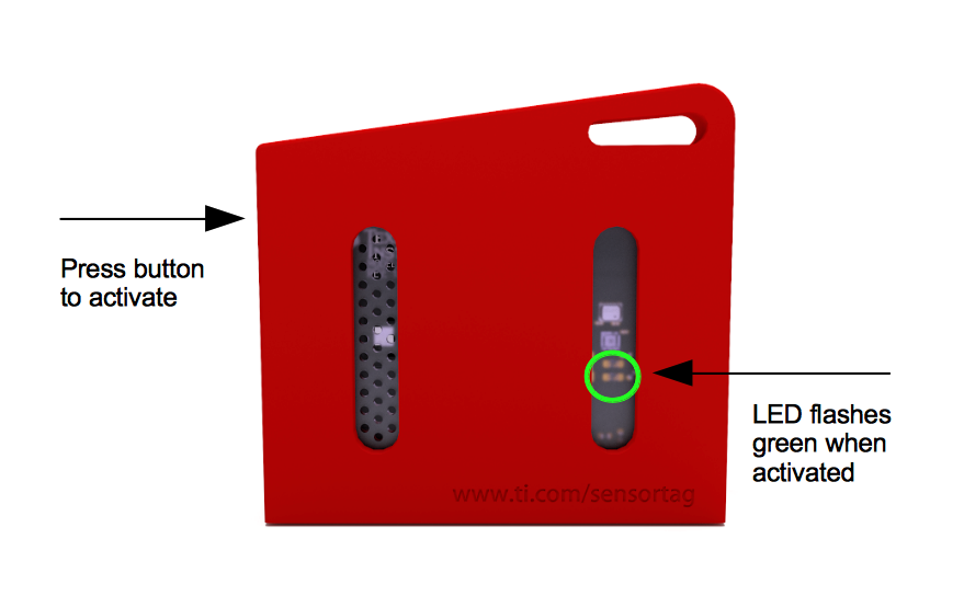
The project basically involves the logging of temperature, pressure, humidity, and light intensity data collected from the Texas Instrument’s sensorTag to an SD Card with the Nano 33 IoT board in between. The TI SensorTag packs many different sensors into a small battery-powered unit and uses Bluetooth Low Energy (BLE) to communicate readings to connected devices like mobile phones, tablets or microcontrollers. It belongs to a new class of sensors that are developed to reduce power consumption, improve portability and eradicate compatibility issues between sensors and microcontrollers. Sensors like the SensorTag are self-contained and possess all they need to exist alone, collecting data and just streaming to whoever calls over BLE. Other communication protocols used by such sensors include BLE, Zigbee, LoRa, and even WiFi.
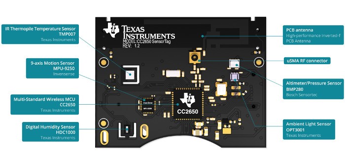
TI SensorTag
The Nano 33 IoT Board comes with onboard wireless features like WiFi and Bluetooth BLE along with an onboard RTC all of which makes it the perfect data-gathering device. The presence of the onboard BLE and the ability of the sensorTag to communicate its data over BLE means we can easily query the SensorTag for the data we require and it will automatically be sent over WiFi. The data received can then be logged on the SD Card.
At the end of today’s tutorial, you would know how to work with the Nano 33 IoT board and also use the TI Sensor Tag.
Required Components
The following components are required to build today’s project;
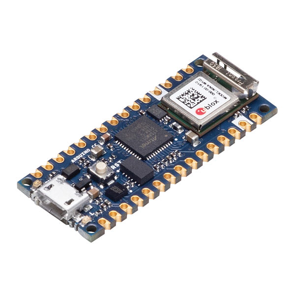
- MKR WiFi 1010 or the Nano 33 IoT board
- TI SensorTag
- SD Card Module
- SD Card
- I2C OLED Display
- Jumper Wires
- Breadboard
For our own build, we will use the Nano 33 sense IoT board, but since it is compatible with the MKR WiFi 1010, on the level at which we will be using it, you can choose to work with the MKR as well.
The exact version of these components used for this tutorial can be bought from the links attached to them.
Schematics
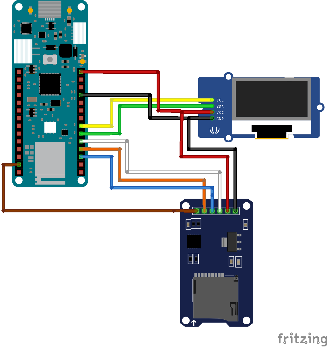
The schematics for this project is quite straight forward. We will connect the SD Card module to the Nano 33 IoT Board via its SPI pins while the OLED display will be connected over I2C. The sensor tag is self-contained and communicates with the microcontroller via Bluetooth as such there will be no physical connection between it and the Nano 33 IoT board.
The schematic showing how the components are connected is provided in the image below:
To make the schematics easier to follow, a pin-pin description of the connection between the components is provided below.
MKR 1010 – SD Card Module
MOSI (D8) - MOSI
MISO(D11) - MISO
SCK() - SCK
D4 - CS
GND - GND
5V - VCC
MKR 1010 – I2C OLED
SDA(D11) - SDA
SCL(D12) - SCL
5V - VCC
GND - GND
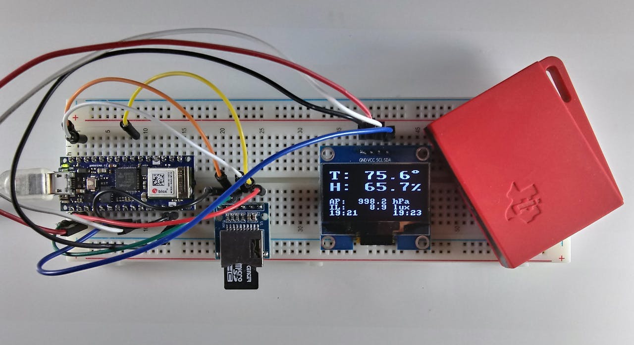
Go over the connections again to ensure everything is as it should be before proceeding to the next section. The setup with everything properly connected should look like the image below.
Code
Based on the goals of the project described under the introduction section, the code for this project is required to query the sensor tag to measure the temperature in Fahrenheit, Relative humidity, barometric pressure, and illumination level of the environment. All of these data are then logged (optional) on the SD Card and displayed on the OLED.
To reduce the amount of work involved, and help optimize the code, we will use Arduino libraries like; the WiFiNINA v1.40 library, the ArduinoBLE library (v1.1.1), RTCZero library (1.6.0), the SD library (v1.2.3), and the U8g2 library. All the libraries can either be installed via the Arduino IDE or downloaded from the links attached to them. The versions of the libraries are added so you can get their exact version as some of them have backward compatibility issues so getting an older or newer version of that same library might not work.
The WiFiNINA library is used to perform all the WiFi related tasks associated with the project while the ArduinoBLE Library facilitates interaction with the SensorTag. The RTCZero library helps with tracking time so the data stored can be timestamped while the SD library facilitates logging the data and the U8G2 library handles the display of that data on the OLED.
With all the libraries installed, we can now proceed to write the code for the project.
As usual, I will do a quick run through the code to explain parts of it that could be difficult.
We start the code by including all the required libraries. These are the same libraries discussed above.
include <WiFiNINA.h>
#include <RTCZero.h>
#include <ArduinoBLE.h>
#include <SPI.h>
#include <SD.h>
#include <U8x8lib.h>
#include <avr/dtostrf.h> // needed for MKR1010
Next, we create an instance of some of the libraries to be used to reference them in our code.
RTCZero rtc;
BLEDevice peripheral;
File SDF;
U8X8_SH1106_128X64_NONAME_HW_I2C u8x8(U8X8_PIN_NONE);
Next, we create a global structure to hold the data obtained from the SensorTag.
// Global structure to hold the sensor data
struct DATA {
  float tem;     // HDC1000 temperature F
  float hum;     // HDC1000 relative humidity %RH
  float bptemp;  // BMP 280 die temperature F
  float bp;      // BMP 280 barometric pressure in hectoPascals (1 hPa = 100 Pa)
  float li;      // OPT3001 lux
  float temd;    // TMP007 die temperature F
  float temo;    // TMP007 object temperature F
};
We also create a bunch of other variables all of which are properly commented with the purpose which they serve properly stated.
// lcd vars
char degree[] = {0xb0, 0x00};
char percent[] = {0x25, 0x00};
char p_buffer[12] = {0, 0, 0, 0, 0, 0, 0, 0, 0, 0, 0, 0};

// clock change catcher
int lastmin;

// for RTC
unsigned long epoch;
int numberOfTries = 0, maxTries = 6;

int status = WL_IDLE_STATUS;  // WiFiNINA use

// Common user-changeable switches
const int GMT = -4; //change this to adapt it to your time zone
byte SDswitch = 1;  // SDswitch 1=ON (write to SD) or 0 (Do not write to SD)
char fname[] = "STDATA.txt"; // data log file Name

//period defines the length of time between measurements in milliseconds
// note that this does not includes delays for sensor reads (~8.7 sec)
long period = 600000L; // 10 minutes
//long period = 5000L;  // 5 sec for testing
Next, we specify the credentials (SSID and Password) of your WiFi access point through which the device is able to connect to the internet. Provide the Key Index if the WiFi security is WEP.
char ssid[] = "";   // your network SSID (name)
char pass[] = "";   // your network password (use for WPA, or use as key for WEP)
int keyIndex = 0;             // your network key Index number (needed only for WEP)
Next, we create SensorTag Characteristics definition to help us pull data from specific sensors. The description for each of the characteristic definitions can be found in sensorTag’s datasheet. You can go through it to know what to call to get data from a particular sensor.
// BMP280
BLECharacteristic BPConCharacteristic;
BLECharacteristic BPValCharacteristic;
// OPT3001
BLECharacteristic OPTConCharacteristic;
BLECharacteristic OPTValCharacteristic;
// TMP007
BLECharacteristic IRTConCharacteristic;
BLECharacteristic IRTValCharacteristic;
// HDC1000
BLECharacteristic HUMConCharacteristic;
BLECharacteristic HUMValCharacteristic;
With this done, we are now ready to write the void setup() function.
We start the function by initializing the OLED via the U82g library, setting the font with which text is displayed and displaying a string “YADL Starting..” to serve as a splash screen.
Next, we initialize serial communication to provide an avenue for debugging via the serial monitor. The code is delayed for a few seconds after every restart to allow the user to launch the serial monitor before data display commences.
#ifdef DEBUG
  Serial.begin(9600);
  delay(5000);  // delay for user to open the serial monitor
  Serial.println("YADL MKR1010/NANO IOT 33 SensorTag Data Logger");
  Serial.println();
#endif
The use of the SD Card is optional so next, we write the code to check/state the users preferred option. If you do not want to use an SD card to save the data, you can eliminate that function by setting the value of the SDswitch variable to “0” but by default, the option to write to the SD is on(“1”). If the option is 1, then the code checks to confirm that an SD card is inserted and working. If not, an error (“No SD Card”) will be displayed and execution goes no further, but if the Card is present and functional, the system continues its operation.
 // check the SD card
  if (SDswitch == 1) {
    if (!SD.begin(4)) {
      u8x8.drawString(0, 2 , "No SD card!");
      u8x8.drawString(0, 3 , "Terminal Error!");
#ifdef DEBUG
      Serial.println("SD Card initialization failed!");
#endif
      while (1);
    }
    else {
      u8x8.drawString(0, 2 , "SD card found. ");
      delay(2000);    // to let user know
      u8x8.drawString(0, 2 , "               ");
#ifdef DEBUG
      Serial.println("SD Card found");
#endif
    }
  }
  else {
    u8x8.drawString(0, 2 , "No SD card");
    u8x8.drawString(0, 3 , "option");
    delay(2000);    // to let user know
    u8x8.drawString(0, 2 , "          ");
    u8x8.drawString(0, 3 , "      ");
#ifdef DEBUG
    Serial.println("No SD Card option");
#endif
  }
Next, we confirm the active status of the onboard WIFi module and if available we connect to the access point using the credentials provided earlier. The connection status is displayed and the board’s WiFi capability is used to contact a time server to get the current epoch. Note that you can correct this epoch for your time zone and DST setting (see program variable GMT). Once the epoch is obtained, the onboard real-time-clock (RTC) is set and used to keep the time.
  // check if the WiFi module works
  if (WiFi.status() == WL_NO_SHIELD) {
#ifdef DEBUG
    Serial.println("WiFi shield not present");
#endif
    u8x8.drawString(0, 1 , "NO WiFi!");
    u8x8.drawString(0, 2 , "Terminal Error!");
    // don't continue:
    while (true);
  }

  // attempt to connect to WiFi network:
  u8x8.drawString(0, 2 , "Connecting.....");
  while ( status != WL_CONNECTED) {
#ifdef DEBUG
    Serial.print("Attempting to connect to SSID: ");
    Serial.println(ssid);
#endif
    // Connect to WPA/WPA2 network. Change this line if using open or WEP network:
    status = WiFi.begin(ssid, pass);
    delay(10000); // wait 10 seconds for connection:
  }
  u8x8.drawString(0, 3 , "Connected!     ");
#ifdef DEBUG
  printWiFiStatus(); // you're connected now, so print out the status:
#endif
  rtc.begin();
  do {
    epoch = WiFi.getTime();
    numberOfTries++;
  }
  while ((epoch == 0) && (numberOfTries < maxTries));

  if (numberOfTries == maxTries) {
    u8x8.drawString(0, 4 , "NTP Unreachable");
    u8x8.drawString(0, 5 , "TERMINAL ERROR!");
#ifdef DEBUG
    Serial.print("NTP unreachable!!");
#endif
    while (1);
  }
  else {
    u8x8.drawString(0, 4 , "Got NTP Epoch  ");
    epoch = epoch + (GMT * 3600UL); // adjust offset for TZ/DST
    rtc.setEpoch(epoch);
#ifdef DEBUG
    Serial.print("Epoch received: ");
    Serial.print(epoch);
    Serial.print(" ");
    printP02D(rtc.getHours());
    Serial.print(":");
    printP02D(rtc.getMinutes());
    Serial.print(":");
    printP02D(rtc.getSeconds());
    Serial.print(" ");
    Serial.print(rtc.getDay());
    Serial.print("/");
    Serial.print(rtc.getMonth());
    Serial.print("/");
    Serial.print(rtc.getYear());
    Serial.println();
#endif
After the time epoch has been received and the RTC corrected, WiFi is ended and BLE begins. Since both of the boards have WiFi and BLE capability, this is easily accomplished.
    WiFi.end();
    delay(15000);
    u8x8.drawString(0, 5 , "WiFi Ended     ");
    u8x8.drawString(0, 6 , "Starting BLE   ");
    delay(2000); // to see it on the screen
#ifdef DEBUG
    Serial.println("WiFi.end executed");
#endif
  }
  // Try to initialize BLE
  if (!BLE.begin()) {
    Serial.println("Terminal Error: Could not start BLE!");
    u8x8.clear();
    u8x8.drawString(0, 0 , "BLE Start Fail");
    u8x8.drawString(0, 1 , "Terminal Error!");
    while (1);
  }
Finally, for the void setup(), the BLE is put into scan mode and the user is notified of the mode via the OLED display.
Next, we move to the void loop() function. We start the function by running scans to see if a Bluetooth device is available. If it is, then we check if it is the SensorTag and we attempt to connect when it is found.
void loop() {
  long lastMillis = 0;  // for period test
  long nowMillis = 0;   // for period test

  // check if a peripheral has been discovered
  peripheral = BLE.available();
  if (peripheral) {
    // discovered a peripheral, print out address and local name
#ifdef DEBUG
    Serial.print("Found ");
    Serial.print(peripheral.address());
    Serial.print(" '");
    Serial.print(peripheral.localName());
    Serial.println("' ");
#endif
    if (peripheral.localName() == "CC2650 SensorTag") {
      BLE.stopScan(); // stop scanning
      // connect to the peripheral
      u8x8.drawString(0, 1 , "Connecting....");
#ifdef DEBUG
      Serial.print("Connecting to SensorTag ...");
#endif
      if (peripheral.connect()) {
        u8x8.drawString(0, 2 , "Connected.....");
#ifdef DEBUG
        Serial.println("Connected...");
#endif
With the SensorTag now connected, we proceed to read the various sensors and write the data to the SD Card using the Write_SDdata function.
while (peripheral.connected()) {
    read_BP(peripheral);
    read_OPT(peripheral);
    read_IRT(peripheral);
    read_HUM(peripheral);
    if (SDswitch) write_SDdata(); // write data to sd card
    // screen for debug no print here as well
At this point, it is important to note that there are different versions of the SensorTag CC2650 and some newer versions may not include the TMP007 sensor like the one used for this project. If that is the case, all you need do is comment out the program references to that unavailable sensor.
With the data logged on the SD, it is then displayed on the OLED and also on the serial monitor.
#ifdef DEBUG
      print_data();
#endif
      print_screenValues();
      printclockD(1); // Update sensor clock
      printclockD(2); // update current clock
      lastmin = rtc.getMinutes();
      lastMillis = millis();
      // stay here until the period is up
      // update current time here
      while ( ( (nowMillis = millis()) - lastMillis) <= period) {
        // need to update the clock here
        if (lastmin != rtc.getMinutes()) {
          lastmin = rtc.getMinutes();
          printclockD(2); // update current clock
        }
      }
    }
The buffer is cleared and the scan process is repeated.
    // peripheral disconnected, start scanning again
    u8x8.clear();
    u8x8.drawString(0, 2 , "Scanning......");
#ifdef DEBUG
    Serial.println(" - rescan...");
#endif
    BLE.scan();
  }
}
The remaining part of the sketch represents the code snippets for the functions that were called within the setup() and loop() functions.
// BLE SensorTag routines
void do_discovery(BLEDevice peripheral) {
  // discover the peripheral's attributes that we want
  // barometric
#ifdef DEBUG
  Serial.print("Discovering attributes for Barometric Pressure service ...");
#endif
  if (peripheral.discoverService("f000aa40-0451-4000-b000-000000000000")) {
#ifdef DEBUG
    Serial.println("discovered");
#endif
    BPConCharacteristic = peripheral.characteristic("f000aa42-0451-4000-b000-000000000000");
    BPValCharacteristic = peripheral.characteristic("f000aa41-0451-4000-b000-000000000000");
  }
  else  {
#ifdef DEBUG
    Serial.println("ERROR: Barometric Pressure service discovery failed.");
#endif
    peripheral.disconnect();
    return;
  }
  // discover the peripheral's attributes that we want
  // optical sensor
#ifdef DEBUG
  Serial.print("Discovering attributes for Luxometer service ...");
#endif
  if (peripheral.discoverService("f000aa70-0451-4000-b000-000000000000")) {
#ifdef DEBUG
    Serial.println("discovered");
#endif
    OPTConCharacteristic = peripheral.characteristic("f000aa72-0451-4000-b000-000000000000");
    OPTValCharacteristic = peripheral.characteristic("f000aa71-0451-4000-b000-000000000000");
  }
  else  {
#ifdef DEBUG
    Serial.println("Error: Luxometer service discovery failed.");
#endif
    peripheral.disconnect();
    return;
  }
  // IR
#ifdef DEBUG
  Serial.print("Discovering attributes for Infrared service ...");
#endif
  if (peripheral.discoverService("f000aa00-0451-4000-b000-000000000000")) {
#ifdef DEBUG
    Serial.println("discovered");
#endif
    IRTConCharacteristic = peripheral.characteristic("f000aa02-0451-4000-b000-000000000000");
    IRTValCharacteristic = peripheral.characteristic("f000aa01-0451-4000-b000-000000000000");
  }
  else  {
#ifdef DEBUG
    Serial.println("Error: Infrared service discovery failed.");
#endif
    peripheral.disconnect();
    return;
  }
  // humidity
#ifdef DEBUG
  Serial.print("Discovering attributes for Humidity service ...");
#endif
  if (peripheral.discoverService("f000aa20-0451-4000-b000-000000000000")) {
#ifdef DEBUG
    Serial.println("discovered");
#endif
    HUMConCharacteristic = peripheral.characteristic("f000aa22-0451-4000-b000-000000000000");
    HUMValCharacteristic = peripheral.characteristic("f000aa21-0451-4000-b000-000000000000");
  }
  else  {
#ifdef DEBUG
    Serial.println("Error: Humidity service discovery failed.");
#endif
    peripheral.disconnect();
    return;
  }
}

// Sensor reads
void read_BP(BLEDevice peripheral) {
  uint8_t holdvalues[6];

  if (peripheral.connected()) {
    // wake up the sensor
    BPConCharacteristic.writeValue(sensorOn);
    delay(1200); // wait for the sensor to do a read
    BPValCharacteristic.readValue(holdvalues, 6);
    unsigned long rawbptemp = (holdvalues[2] * 65536) + (holdvalues[1] * 256) + holdvalues[0];
    unsigned int rawbp = (holdvalues[5] * 65536) + (holdvalues[4] * 256) + holdvalues[3];
    // sleep sensor
    BPConCharacteristic.writeValue(sensorOff);
    // calculate temperature and pressure final values
    float bptemp = ((double)rawbptemp / 100.0);
    bptemp = ((bptemp * 9.0) / 5.0) + 32.0; // convert to F - comment out to leave at C
    float bp = ((double)rawbp / 100.0);
    // save into the structure
    SensorData.bp = bp;
    SensorData.bptemp = bptemp;
  }
  else {
#ifdef DEBUG
    Serial.println(" *not connected* ");
#endif
  }
}

void read_OPT(BLEDevice peripheral) {
  // in this version the characteristic's value is read directly
  // into rawlux and then processed. No array is used.

  uint16_t rawlux;

  if (peripheral.connected()) {
    // wake up the sensor
    OPTConCharacteristic.writeValue(sensorOn);
    delay(1200); // wait for the sensor to do a read
    OPTValCharacteristic.readValue(rawlux);
    OPTConCharacteristic.writeValue(sensorOff); // sleep sensor
    // calculate lux final value
    unsigned int m = rawlux & 0x0FFF;
    unsigned int e = (rawlux & 0xF000) >> 12;
    float lux = (m * (0.01 * pow(2.0, e)));
    // save into the structure
    SensorData.li = lux;
  }
  else {
#ifdef DEBUG
    Serial.println(" *not connected* ");
#endif
  }
}

void read_IRT(BLEDevice peripheral) {
  uint8_t holdvalues[4];

  if (peripheral.connected()) {
    // wake up the sensor
    IRTConCharacteristic.writeValue((uint8_t) 0x01);
    delay(1200); // wait for the sensor to do a read
    IRTValCharacteristic.readValue(holdvalues, 4);
    unsigned int rawobj = (holdvalues[0]) + (holdvalues[1] * 256);
    unsigned int rawamb = (holdvalues[2]) + (holdvalues[3] * 256);
    IRTConCharacteristic.writeValue(sensorOff); // sleep sensor
    // calculate final temperature values
    const float SCALE_LSB = 0.03125;
    int it = (int)( rawobj >> 2);
    float IRTo = ( (float)it) * SCALE_LSB;
    IRTo = ( (IRTo * 9.0) / 5.0 ) + 32.0; // convert to F - comment out to leave at C
    it = (int)(rawamb >> 2);
    float IRTa = (float)it * SCALE_LSB;
    IRTa = ( (IRTa * 9.0) / 5.0) + 32.0; // convert to F - comment out to leave at C
    // save into the structure
    SensorData.temd = IRTa;
    SensorData.temo = IRTo;
  }
  else {
#ifdef DEBUG
    Serial.println(" *not connected* ");
#endif
  }
}

void read_HUM(BLEDevice peripheral) {
  uint8_t holdvalues[4]; // hold the characteristic's bytes

  if (peripheral.connected()) {
    // wake up sensor
    HUMConCharacteristic.writeValue(sensorOn);
    delay(1200); // wait for the sensor to do a read
    HUMValCharacteristic.readValue(holdvalues, 4);
    HUMConCharacteristic.writeValue(sensorOff); // sleep sensor
    unsigned int rawtem = (holdvalues[0]) + (holdvalues[1] * 256);
    unsigned int rawhum = (holdvalues[2]) + (holdvalues[3] * 256);
    // calculate final temperature and relative humidity values
    float temp = (rawtem / 65536.0) * 165.0 - 40.0;
    temp = ((temp * 9.0) / 5.0) + 32.0; // convert to F - comment out to leave at C
    float hum = ((double)rawhum / 65536.0) * 100.0;
    // save into the structure
    SensorData.tem = temp;
    SensorData.hum = hum;
  }
  else {
#ifdef DEBUG
    Serial.println(" *not connected* ");
#endif
  }
}

// Print serial and screen and write SD routines
void print_data() {
  // Print the data to the serial moniter
  // NOTE: the time vars could be slightly different then the SD card
  // since they are two different routines but the Serial prints are
  // mainly for debugging

  String separator = ", ";
  // Data Line as follow (with comma separator):
  // epoch day, month, year, hours, minutes, seconds, HDC1000 temp, HDC1000 hum,
  // BMP280 pressure, BMP280 tem, OPT3001 light (lux), TMP007 temp, TMP0007 object temp
#ifdef DEBUG
  Serial.print(rtc.getEpoch());
  Serial.print(separator);
  Serial.print(rtc.getDay());
  Serial.print(separator);
  Serial.print(rtc.getMonth());
  Serial.print(separator);
  Serial.print(rtc.getYear());
  Serial.print(separator);
  printP02D(rtc.getHours());
  Serial.print(separator);
  printP02D(rtc.getMinutes());
  Serial.print(separator);
  printP02D(rtc.getSeconds());
  Serial.print(separator);
  Serial.print(SensorData.tem);
  Serial.print(separator);
  Serial.print(SensorData.hum);
  Serial.print(separator);
  Serial.print(SensorData.bp);
  Serial.print(separator);
  Serial.print(SensorData.bptemp);
  Serial.print(separator);
  Serial.print(SensorData.li);
  Serial.print(separator);
  Serial.print(SensorData.temo);
  Serial.print(separator);
  Serial.print(SensorData.temd);
  Serial.println();
  // end of data line
#endif
}

void write_SDdata() {
  // Write the data to the SD card
  String separator = ", ";

  // Data Line as follow (with comma separator):
  // epoch day, month, year, hours, minutes, seconds, HDC1000 temp, HDC1000 hum,
  // BMP280 pressure, BMP280 tem, OPT3001 light (lux), TMP007 temp, TMP0007 object temp
  // open the file
  SDF = SD.open(fname, FILE_WRITE);
  if (!SDF) {
    // terminal error if we can't open the SD File (we already initialized)
    u8x8.clearDisplay();
    u8x8.drawString(0, 2 , "SD Card    ");
    u8x8.drawString(0, 3 , "Terminal Error!");
#ifdef DEBUG
    Serial.println("SD card write failure!");
#endif
    while (1);
  }
  else {
    // write the separator-delimited data line
    // comment out what you don't want e.g.,
    // epoch, day,mon,year,hour,min,sec, HDC tem, HDC hum, AP, BMP tem, Illum, TMP obj Tem, TMP tem
    SDF.print(rtc.getEpoch());
    SDF.print(separator);
    SDF.print(rtc.getDay());
    SDF.print(separator);
    SDF.print(rtc.getMonth());
    SDF.print(separator);
    SDF.print(rtc.getYear());
    SDF.print(separator);
    SDF.print(rtc.getHours());
    SDF.print(separator);
    SDF.print(rtc.getMinutes());
    SDF.print(separator);
    SDF.print(rtc.getSeconds());
    SDF.print(separator);
    SDF.print(SensorData.tem);
    SDF.print(separator);
    SDF.print(SensorData.hum);
    SDF.print(separator);
    SDF.print(SensorData.bp);
    SDF.print(separator);
    SDF.print(SensorData.bptemp);
    SDF.print(separator);
    SDF.print(SensorData.li);
    SDF.print(separator);
    SDF.print(SensorData.temo);
    SDF.print(separator);
    SDF.print(SensorData.temd);
    SDF.println();  // Windows cr/lf
    SDF.close();
  }
}

void print_screenT() {
  // print the LCD template
  u8x8.setFont(u8x8_font_px437wyse700a_2x2_f);   // large for Tem/Hum
  u8x8.drawString(0, 0, "T:");
  u8x8.drawUTF8(14, 0, degree);
  u8x8.drawString(0, 2, "H:");
  u8x8.drawUTF8(14, 2, percent);
  // back to smaller font for tyhe rest
  u8x8.setFont(u8x8_font_amstrad_cpc_extended_f);
  u8x8.drawString(0, 5, "AP:");
  //u8x8.drawString(0, 5, "BP:    0123 hPa");
  u8x8.setCursor(10, 5);
  u8x8.print(" hPa");
  u8x8.drawString(0, 6, "IL:");
  u8x8.setCursor(10, 6);
  u8x8.print(" lux");
  // alternative times current left
  u8x8.drawString(0, 7, "00:00");
  u8x8.drawString(11, 7, "00:00");
}

void print_screenValues() {
  float Dtem, Dhum, Dap, Dli;
  // call this *after* sensor structure has been updated
  // first update the logged time? need small font
  u8x8.setFont(u8x8_font_px437wyse700a_2x2_f);   // large for Tem/Hum
  // temperature
  // sensor error check NOTE: read values will be printed to screen and SD
  Dtem = SensorData.tem;
  if (Dtem > 999.9) Dtem = 999.9;
  if (Dtem < -99.9) Dtem = -99.9;
  dtostrf(Dtem, 5, 1, p_buffer); // convert to 5 chars 1 after decimal
  u8x8.setCursor(4, 0);
  u8x8.print(p_buffer);
  //u8x8.drawUTF8(14, 0, degree); degree sign has been done in
  // humidity
  // sensor error check
  Dhum = SensorData.hum;
  if (Dhum > 100.0) Dhum = 100.0;
  if (Dhum < 0.0) Dhum = 0.0;
  dtostrf(Dhum, 5, 1, p_buffer); // convert to 5 chars 1 after decimal
  u8x8.setCursor(4, 2);
  u8x8.print(p_buffer);
  //u8x8.drawUTF8(14, 2, percent);  already done in template print
  // back to smaller font for tyhe rest
  u8x8.setFont(u8x8_font_amstrad_cpc_extended_f);
  // barometric pressure
  // sensor error check
  Dap = SensorData.bp;
  if (Dap < 750.0) Dap = 000.0;
  if (Dap > 1200.0) Dap = 9999.9;
  dtostrf(Dap, 7, 1, p_buffer); // convert to 7 chars 1 after decimal
  u8x8.setCursor(3, 5);
  u8x8.print(p_buffer);
  // Illuminance
  // sensor error check
  Dli = SensorData.li;
  if (Dli > 99999.9) Dli = 99999.9;
  if (Dli < 0.0) Dli = 0;
  dtostrf(Dli, 7, 1, p_buffer); // convert to 7 chars 1 after decimal
  u8x8.setCursor(3, 6);
  u8x8.print(p_buffer);
}

void printclockD(byte side) {
  // print the HH:SS of the current clock on the right or left side of the LCD
  // must be in a small font! (could do this as a switch case)
int hourT,minT;

  switch (side) {
    case 1: //left side
      u8x8.setCursor(0, 7);
      hourT = rtc.getHours();
      if (hourT < 10) { // pad hours <10
        u8x8.drawString(0, 7 , "0");
        u8x8.setCursor(1, 7);
        u8x8.print(hourT);
      }
      else {
        u8x8.print(hourT);
      }
      // note the ':' is from the template
      u8x8.setCursor(3, 7);
      minT = rtc.getMinutes();
      if (minT < 10) { // pad seconds <10
        u8x8.drawString(3, 7 , "0");
        u8x8.setCursor(4, 7);
        u8x8.print(minT);
      }
      else {
        u8x8.print(minT);
      }
      break;
    case 2: // right side
      u8x8.setCursor(11, 7);
      hourT = rtc.getHours();
      if (hourT < 10) { // pad hours <10
        u8x8.drawString(11, 7 , "0");
        u8x8.setCursor(12, 7);
        u8x8.print(hourT);
      }
      else {
        u8x8.print(hourT);
      }
      // note the ':' is from the template
      u8x8.setCursor(14, 7);
      minT = rtc.getMinutes();
      if (minT < 10) { // pad secondss <10
        u8x8.drawString(14, 7 , "0");
        u8x8.setCursor(15, 7);
        u8x8.print(minT);
      }
      else {
        u8x8.print(minT);
      }
      break;
    default:  // can add other options
      // statements
      break;
  }
}

void printWiFiStatus() {
  // note: this will only be called if DEBUG is defines
  Serial.print("SSID: ");
  Serial.println(WiFi.SSID());
  IPAddress ip = WiFi.localIP();
  Serial.print("IP Address: ");
  Serial.println(ip);
  long rssi = WiFi.RSSI();
  Serial.print("signal strength (RSSI):");
  Serial.print(rssi);
  Serial.println(" dBm");
}

void printP02D(int number) {
  if (number < 10) Serial.print('0');
  Serial.print(number);
}
The code is a bit bulky as such, the complete code for the project is attached under the download section.
Demo
With the sketch complete, verify it to ensure there are no errors, then go over the schematics once again to ensure everything is as it should be. With that done, connect the Nano 33 IoT or the MKR WiFi 1010 to your computer and upload the sketch to it. As soon as the upload is complete, open your serial monitor for debugging, and turn on the SensorTag ensuring its within reasonable distance for Bluetooth connection to your Nano 33 IoT setup.
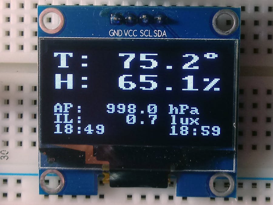
From the serial monitor and the OLED, you should see the SensorTag connect to the Nano 33 sense IoT and you should see the data displayed on the OLED as shown below.
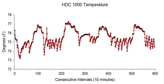
The data should also now be stored in a CSV format on the attached SD card too with timestamps that reflect the time as maintained by the RTC, and you should be able to plot it as shown in the image below.
Going Forward
While IoT provides a good way to receive data immediately and perform analysis in real-time, there are situations where it becomes impractical to send the data in real-time. For such a situation the data can be logged and then transmitted in due time, which can be achieved with a setup similar to the one described in this tutorial. Also, more sensors like the SensorTags are being developed with some based on connectivity solutions with longer ranges like LoRa. Having all of these in place means a scenario where a single datalogger can be used for multiple sensors that can be achieved.
That’s all for today’s project. Thanks for building along. Feel free to reach out to me with whatever questions you might have, via the comment section.