3 Phase AC Motor Controller
This project made using MC3PHAC from NXP Semiconductor. The project generates 6 PWM signals for 3 Phase AC Motor controller.
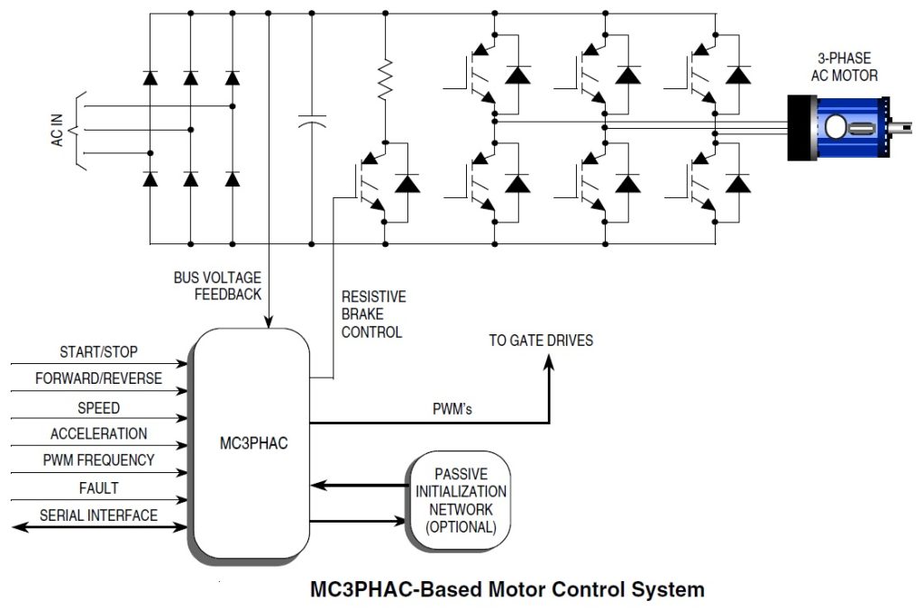
This project made using MC3PHAC from NXP Semiconductor. The project generates 6 PWM signals for 3 Phase AC Motor controller. It’s very easy to make professional VFD combining with Intelligent Power Module (IPM) or 3 Phase IGBT/MOSFET with Gate driver. The board provides 6 PWM signals for the IPM or IGBT Inverter and also brake signal. Also this board works in stand-alone mode and doesn’t require any software programming/coding.
The MC3PHAC is a high-performance monolithic intelligent motor controller designed specifically to meet the requirements for low-cost, variable-speed, 3-phase ac motor control systems. The device is adaptable and configurable, based on its environment. It contains all of the active functions required to implement the control portion of an open loop, 3-phase ac motor drive. One of the unique aspects of this board is that although it is adaptable and configurable based on its environment, it does not require any software development. This makes the MC3PHAC a perfect fit for customer applications requiring ac motor control but with limited or no software resources available.
Included in the MC3PHAC are protective features consisting of dc bus voltage monitoring and a system fault input that will immediately disable the PWM module upon detection of a system fault.
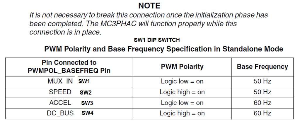
All outputs are TTL signals, Input supply 5-15V DC, DC Bus voltage should be between 1.75V-4.75V, Dip switch provided to set the motor frequency 60 or 50 Hz, jumpers also helps to set the polarity of the output PWM Active Low or Active High and this helps to use this board with any kind of IPM modules since output can be set active low or high. Potentiometer PR2 helps to adjust motor speed. Refer to datasheet of the IC to change base frequency, PWM Dead Time, other possible parameters.
Speed Control — the synchronous motor frequency can be specified in real time to be any value from 1 Hz to 128 Hz by adjusting the PR2 potentiometer. The scaling factor is 25.6 Hz per volt. The SPEED pin is processed by a 24-bit digital filter to enhance the speed stability in noisy environments.
Acceleration Control — Motor acceleration can be specified in real time to be in the range from 0.5 Hz/second, ranging to 128 Hz/second, by adjusting the PR1 potentiometer. The scaling factor is 25.6 Hz/second per volt.
Fault Protection: The MC3PHAC supports an elaborate range of fault protection and prevention features. If a fault does occur, the MC3PHAC immediately disables the PWMs and waits until the fault condition is cleared before starting a timer to re-enable the PWMs. Refer to the graph in Figure 10 for the resistance value versus retry time from data sheet of the IC. Figure 10 assumes a 6.8 kΩ pull up resistor. In standalone mode, this timeout interval is specified during the initialization phase by supplying a voltage to the MUX_IN pin while the RETRY_TxD pin is being driven low. In this way, the retry time can be specified from 1 to 60 seconds, with a scaling factor of 12 seconds per volt
External Fault Monitoring: The FAULTIN pin accepts a digital signal that indicates a fault has been detected via external monitoring circuitry. A high level on this input results in the PWMs being immediately disabled. Typical fault conditions might be a dc bus over voltage, bus over current, or over temperature. Once this input returns to a logic low level, the fault retry timer begins running, and PWMs are re-enabled after the programmed timeout value is reached. FLTIN input pin 9 of the connecter CN3 should be high to bring the fault pin low for normal operation.
Bus Voltage Integrity Monitoring ( Input Pin 10 of the CN3) The DC_BUS pin is monitored at a 5.3 kHz frequency (4.0 kHz when the PWM frequency is set to 15.9 kHz), and any voltage reading outside of an acceptable window constitutes a fault condition. In standalone mode, the window thresholds are fixed at 4.47 volts (128 percent of nominal), and 1.75 volts (50 percent of nominal), where nominal is defined to be 3.5 volts. Once the DC_BUS signal level returns to a value within the acceptable window, the fault retry timer begins running, and PWMs are re enabled after the programmed timeout value is reached. During power-up, it is possible that VDD could reach operating voltage before the dc bus capacitor charges up to its nominal value. When the dc bus integrity is checked, an under voltage would be detected and treated as a fault, with its associated timeout period. To prevent this, the MC3PHAC monitors the dc bus voltage during power-up in standalone mode, and waits until it is higher than the under voltage threshold before continuing. During this time, all MC3PHAC functions are suspended. Once this threshold is reached, the MC3PHAC will continue normally, with any further under voltage conditions treated as a fault.
Note : If dc bus voltage monitoring is not desired, a voltage of 3.5 volts ± 5 percent should be supplied to the DC_BUS pin. To do this Use following components, R2 Should be 3.3Kohms, R4 4K7 Ohms, C6 0.1uF and close jumper between pin1 and pin 2.
Regeneration Control — Regeneration is a process by which stored mechanical energy in the motor and load is transferred back into the drive electronics, usually as a result of an aggressive deceleration operation. In special cases where this process occurs frequently (for example, elevator motor control systems), it is economical to incorporate special features in the motor drive to allow this energy to be supplied back to the ac mains. However, for most low cost ac drives, this energy is stored in the dc bus capacitor by increasing its voltage. If this process is left unchecked, the dc bus voltage can rise to dangerous levels, which can destroy the bus capacitor or the transistors in the power inverter. The MC3PHAC incorporates two techniques to deal with regeneration before it becomes a problem.
Resistive Braking: The DC_BUS pin is monitored at a 5.3 kHz frequency (4.0 kHz when the PWM frequency is set to 15.9 kHz), and when the voltage reaches a certain threshold, the RBRAKE pin is driven high. This signal can be used to control a resistive brake placed across the dc bus capacitor, such that mechanical energy from the motor will be dissipated as heat in the resistor versus being stored as voltage on the capacitor. In standalone mode, the DC_BUS threshold required to assert the RBRAKE signal is fixed at 3.85 volts (110 percent of nominal) where nominal is defined to be 3.5 volts.
Selectable PWM Frequency: The MC3PHAC accommodates four discrete PWM frequencies and can be changed dynamically while the motor is running. This resistor can be a potentiometer or a fixed resistor in the range shown in Table In standalone mode, the PWM frequency is specified by applying a voltage to the MUX_IN pin while the PWM FREQ_RxD pin is being driven low. Table 4 from data sheet shows the required voltage levels on the MUX_IN pin and the associated PWM frequency for each voltage range.
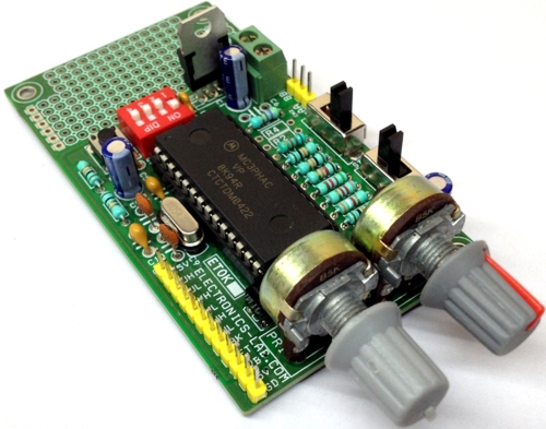
- PR1: Potentiometer to set the Acceleration
- PR2: Potentiometer for speed adjust
- SW1: DIPX4 Switch to set the Frequency 60Hz/50Hz and Also Active low/Active High Output
- SW2: Reset Switch
- SW3: Start/Stop Motor
- SW4: Direction Change CW/CCW of the Motor
- CN1: DC Supply Input 7-15V DC
- CN2: Bus Voltage Feed from IPM/IGBT Module for Over/Under Voltage Protection
- CN3: Interface between IPM Module/IGBT Board Provides 6PWM Out, Brake out and Fault In
- PCB has prototype area that can be used for development.
Features
- Supply 7-15V DC
- Potentiometer provided to control the Motor Speed
- Default PWM Frequency 10.582 KHz , Can be Adjust between ( 5.291 kHz – 164 kHz)
- Potentiometer For Acceleration Adjust
- Slide Switch for Direction Control
- Slide Switch for Start/Stop
- 6 PWM Signals Output
- Default dead time 4.5uS
- Fault Retry Time 32.8 Seconds
- VBS Input (Bus Voltage Feedback) Under Voltage Control
- Fault In ( Over Current or Short Circuit Input)
- Volts-per-Hertz speed control
- Digital signal processing (DSP) filtering to enhance speed stability
- 32-bit calculations for high-precision operation
- Internet enabled
- No user software development required for operation
- 6-output pulse-width modulator (PWM)
- 3-phase waveform generation
- 4-channel analog-to-digital converter (ADC)
- User configurable for standalone
- Dynamic bus ripple cancellation
- Selectable PWM polarity and frequency
- Selectable 50/60 Hz base frequency
- Phase-lock loop (PLL) based system oscillator
- Low-power supply voltage detection circuit
- Included in the MC3PHAC are protective features consisting of dc bus voltage monitoring and a system
- Fault input that will immediately disable the PWM module upon detection of a system fault.
Some target applications for the MC3PHAC include
- Low horsepower HVAC motors
- Home appliances
- Commercial laundry and dishwashers
- Process control
- Pumps and fans
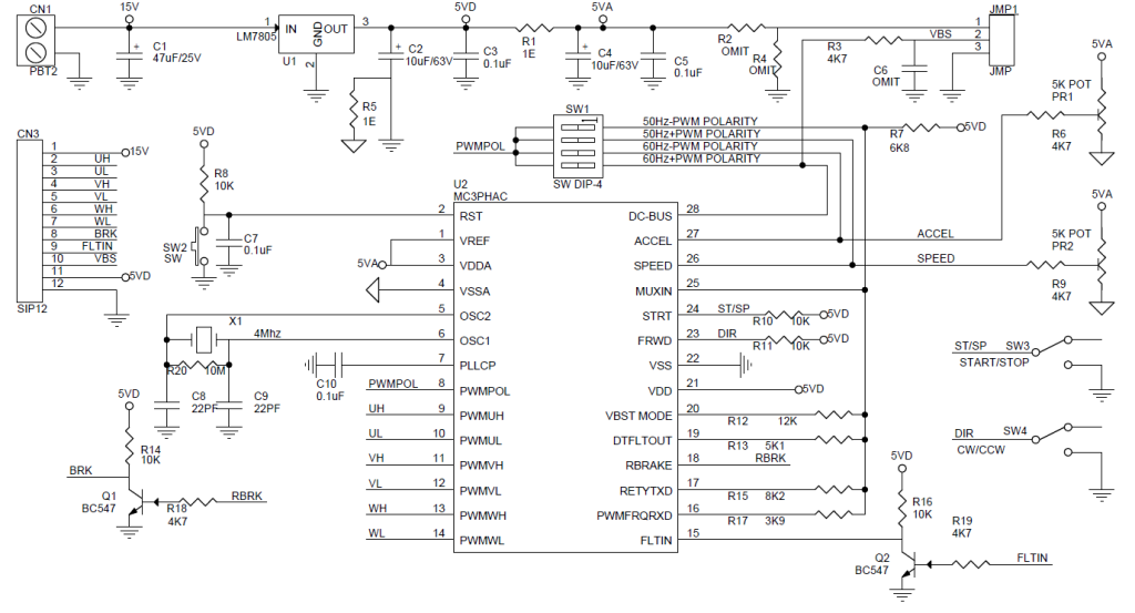
Schematic
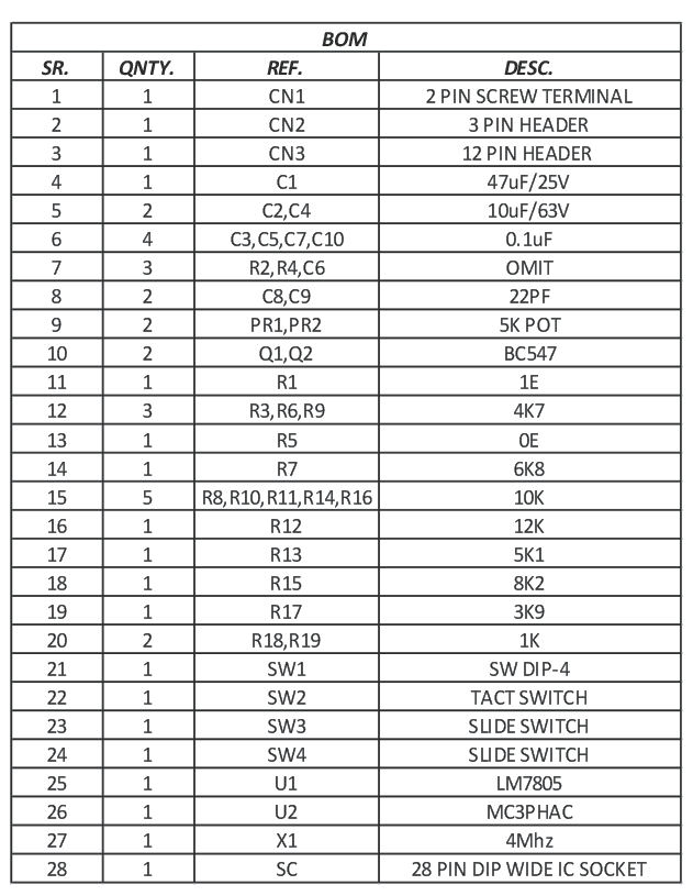
Parts List
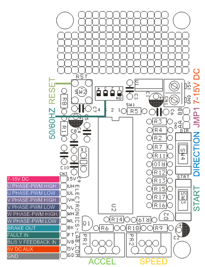
Connections
DIP Switch Settings
Block Diagram
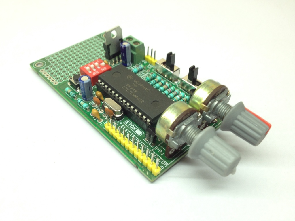
Photos
Where can I get this board to buy and his much in us dollars
We are sorry, we don’t sell kits or ready products.
what is the maximum horsepower motor this can drive?
It depends on the power stage you are going to use. This is going to generate 6 PWM signals for 3 Phase AC Motor controller.
Can we use this to drive 3phase BLDC motor
This can be used as control unit for AC motors only and not BLDC.
is the ic and pcb available anywhere for this circuit, if yes please email the details to stsrfsolutions@gmail.com
I can found it on ebay.com and other online stores but it seems it’s an obsolete part. PCB files (Gerber) are available so you can manufacture your own PCB in your desired manufacture.
its not obsolete part, its available from http://www.nxp.com , its has been taken over by NXP from Freescale
It’s obsolete now, according to the homepage.
It can however be found on Ali Express (Surely on eBay as well), but it’s very expensive, like ~$25, 200 SEK or 20€
Just bought one, waiting for delivery, and some additional components, and I’ll have to order some others too, but soon it’ll run my washing machine!
Does this circuit have pre-driver stages? Thank you
I think it’s not. Datasheet indicates that outputs are connected to separate gate drivers.
Which gate driver for suitable ?
We are going to design and publish a suitable Gate Driver for this Motor Controller. So stay tuned!
how to contact ramkumar sir
You can use the contact us form on the menu above and we will handle communication with Ramkumar, what this is about?
Hello, I would like to know that you connect to the CN3 … when you talk about VBS, what voltage do you mean, Thank you
CN3 provides the output signals to control the gates of output transistors on output stage (not covered on this project) and VBS is the BUS Voltage Feedback that comes from the output stage as shown in the diagram above.
Sir how to purchase this product
We can produce this board if order is > 25 pieces. Contact us using the form on top of page.
Pl mention the Approx Cost for 25 nos Board
Hi. Nice schematic. I’m a bit curious about this brake function. I think it was something mentioned in the YT video, but my Indian English is a bit rusty (Very difficult to understand some parts due to heavy accent!).
I tried google it, but all I got was some online calculator and some PDF’s with mumbo-jumbo super nerd stuff. How is this connected?
Another thing that daunts me, is that this circuit is super high tech, has it’s own RS232 interface, yet it doesn’t have any tachometer input. In my opinion it should have, Would have made sense as some motors have very high RPM’s, and it should be able to count these and regulate thereafter…
So, any input would be greatly appreciated, thank you
HI, how to Adjust pwm Frequency
Check on page 11 of datasheet above. There is a table indicating how to choose the desired frequency.
Is this circuit capable to provide three phase adjustable power supply instead of driving motor?
This board will only produce the 6 PWM signal that are needed to drive the output MOSFETs. I am not sure if it will work a 3-phase power source.
Hi again.
I’m wondering if anyone have had this problem with the MC3PHAC circuit?:
On the Forward/Reverse pin towards earth I get like 5 mVolts constantly, in spite of having 10kOhm pull-up resistors, just as the others for Start/Stop and Reset.
When not powered I get around 15 kOhms towards ground and similar around this pin to other pins, so it’s not shorted out.
There’s enough current running from this pin to run an LED, and even making a 150 Ohm resistor hot, so something isn’t right here.
Now, of course, the Corona virus is on a rampage so import from China, and Italy has been suspended with no end date, so I’m looking at several months in shipping time, maybe, I don’t know.
So, if any kind soul would happen to have an extra laying around I’d be more than happy to buy it, at a reasonable price of course.
Unfortunately we don’t have this IC on hand. Have you searched online from an Europe source?
Tried and failed, so I went crawling back to Ali Express. I got lucky since I’m a gold member there I could get a one-time-refund.
So, a few days later, after even trying a local firm which usually have different connections, I first spoke to a seller on Ali, and tried to get the Corona-virus vs. transportation out of the way, but apparently he didn’t even know about it, but he assured me that it’d be delivered.
Naturally I was hesitant, but thought that I better give it another shot, besides without it I’d still have to search and, most irritating of it all; wait, so I might just as well get the waiting over with.
So, I ordered it last Thursday, and it finally got shipped out today, but it remains to be seen when it’ll move forward, since, apparently according to my postal services (PostNord, Swedish post), China Mail (Also, apparently, known as ESP or whatever abbreviation it was) have issued an halt on any in-person handovers or something like that.
So, it’ll be very interesting to see when I’ll get this, and if the seller heeded my demands on proper ESD precautions and not just a clip-out from the reel in a mere ZIP-bag, like last time (from another seller!).
I really, REALLY need this crap to work this time so I can finally move on with my build and focus on the tricky part – The programming!
Sorry, forgot that I posted this, as I was replying to another user here.
I ended up having some problem that wasn’t related to the actual circuit, but rather the potentiometer that was setting the voltage for the DC rails.
Mischievous at that, as the multi-meter probes affected the voltage, thus measured voltage dropped and missing the “sweet spot” for the active window (Don’t remember the voltages, but somewhere around 4,3V or so I think it was).
I also had an optocoupler that was connected so when I had the circuit connected it was activated and was pulling the For/Rev pin to ground.
In other words; I got it working, and it did so beautifully! The motor got a bit hot, but I would assume that was because I used the wrong resistors for the feedback deal on the driver module.
Since then, as I was about to assemble the machine I discovered that I’d made a grave error of not separate the ground from the AC mains, so I ended up scrapping the PCB entirely and redid the entire design, so now it’s completely different and I did order the PCB’s off JLCPCB this time as it got really complex with three ATMEGA processors (2560, 328 and 32), as well as an additional panel PCB with a dosage pump controller for washing detergents).
So, it got a complex build with all sorts of sensors, and now I’m waiting to place an order of some components, then it’ll get assembled and hopefully it’ll work as I intended.
Hi I am interested in this pcb what is the cost how can i purchase the pcb and companents thanks
In case that I’m not mistaken, you’ll have to make the PCB yourself, and obtain the components for yourself too.
You have several options to make the PCB in several CAD programs.
JLCPCB have an online editor, in which you can import schematics and layouts from various formats.
I would recommend using JLCPCB since they’re cheap, and have a most excellent support staff, but you’ll have to make sure your layout complies with their standards.
So, if you’re unable to do it yourself, ask someone to help you to meet their demands.
But, if you want a faster way of making a PCB, you can always buy one with photo-resist, and some Overhead sheets (Transparent film) and print out these layouts above, expose with UV-lamp, etch and then drill. Not the most easy thing to do, given it’s double sided and need some thinking of how do get it right.
But, practice makes perfect as they say.
For the drilling, I strongly recommend using drill bits that are made specifically for PCB drilling, and not ordinary (You’ll thank me later, I promise!) drills.
You can drill by hand, but it’s easy to break the drill bits, so preferably you should use a drill press for this to get some better control.
As for the MC3PHAC, you can order it from Ali Express and eBay, but it’s quite expensive, at least 20-30 USD plus shipping as it’s obsolete and not made anymore, hence it’s hard to come by.
The other components can cost you a bit of money, so I recommend this build for someone who’s a bit of a hoarder, thus already having a lot of old PCB’s and components to use as donors.
Which software can be used to simulate this circuit?
Can I buy
Hi where will you connect the three phase power
This is only the controller, producing the control signals. The power stage isn’t included and can be an Intelligent Power Module (IPM) or 3 Phase IGBT/MOSFET with Gate driver. Check the block diagram above.
what is the cost for mc3phac board in india