DDS Function Generator
A new implementation of the AVR DDS signal generator v2.0 found at: http://www.scienceprog.com/avr-dds-signal-generator-v20 Introduction This is a new implementation of the AVR DDS signal generator v2.0, already published in scienceprog.com. It is obvious that full credit for the original schematic and the firmware goes to its original creator.
A new implementation of the AVR DDS signal generator v2.0 found at: http://www.scienceprog.com/avr-dds-signal-generator-v20
Introduction
This is a new implementation of the AVR DDS signal generator v2.0, already published in scienceprog.com. It is obvious that full credit for the original schematic and the firmware goes to its original creator. Presented here is a different PCB that is compact, single sided with only through-hole components for easy construction.
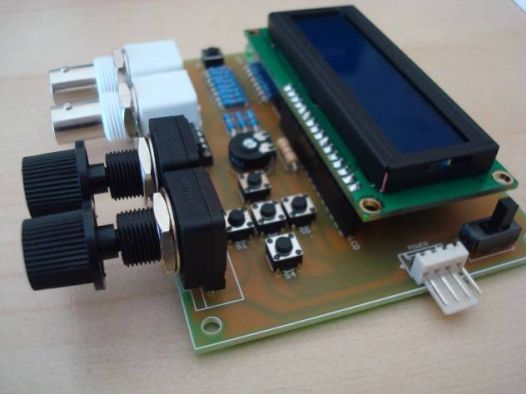
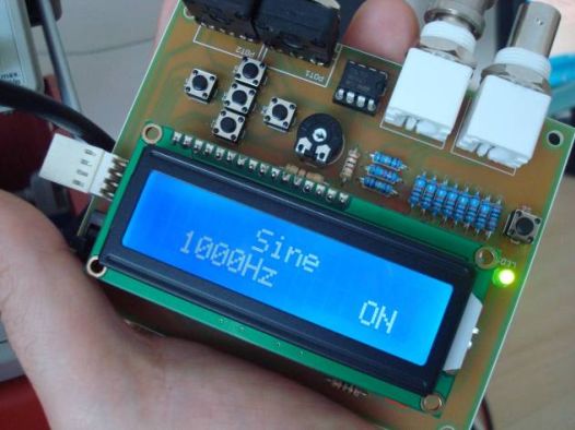
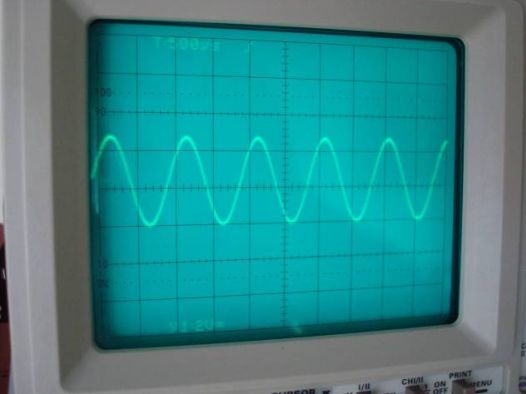
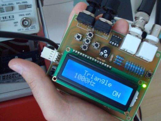
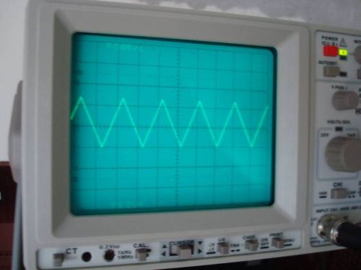
The function generator features two BNC outputs : one for the high speed [1 to 8 MHz] square signal (BNC1) and another for the DDS signal (BNC2). Offset and amplitude can be regulated by two potentiometers : offset in range of +5V to -5V (POT1) and amplitude in range of 0 to 10V (POT2). Up and down arrow buttons are used for changing the function type (sine, triangle etc.) while left and right arrow buttons are used for changing the frequency value. There is also a separate menu for changing frequency step. When the middle button is pressed, the signal generation starts. Middle button is pressed again for stopping the signal. More details can be found in the original site.
Schematic
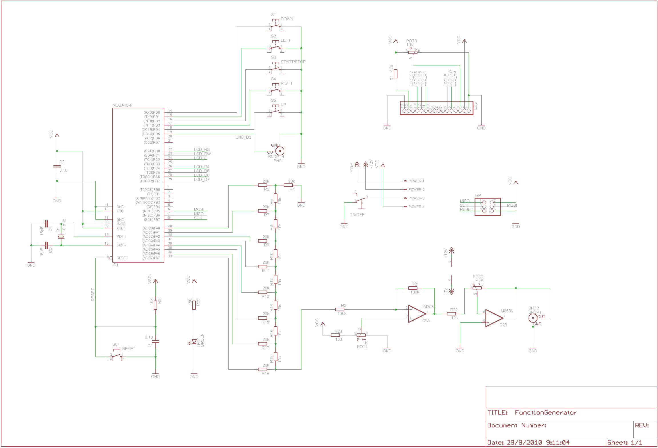
EAGLE Schematic (only a status led and an on/off switch was added)
Parts
| Part | Value |
| R1 | 470 Ω ½W 5% |
| R2 | 10 ΚΩ ¼W 5% |
| R3 | 100 ΚΩ ¼W 1% |
| R4 | 20 ΚΩ ¼W 1% |
| R5 | 20 ΚΩ ¼W 1% |
| R6 | 10 ΚΩ ¼W 1% |
| R7 | 20 ΚΩ ¼W 1% |
| R8 | 10 ΚΩ ¼W 1% |
| R9 | 20 ΚΩ ¼W 1% |
| R10 | 10 ΚΩ ¼W 1% |
| R11 | 20 ΚΩ ¼W 1% |
| R12 | 10 ΚΩ ¼W 1% |
| R13 | 20 ΚΩ ¼W 1% |
| R14 | 10 ΚΩ ¼W 1% |
| R15 | 20 ΚΩ ¼W 1% |
| R16 | 10 ΚΩ ¼W 1% |
| R17 | 20 ΚΩ ¼W 1% |
| R18 | 10 ΚΩ ¼W 1% |
| R19 | 20 ΚΩ ¼W 1% |
| R20 | 100 Ω ¼W 5% |
| R21 | 100 ΚΩ ¼W 1% |
| R22 | 12 ΚΩ ¼W 1% |
| R23 | 150 Ω ¼W 5% |
| POT1 | 1 ΚΩ linear potentiometer |
| POT2 | 47 KΩ linear potentiometer |
| POT3 | 10 ΚΩ trimmer |
| C1 | 100 nF MKT/polyester |
| C2 | 100 nF MKT/polyester |
| C3 | 18 pF ceramic |
| C4 | 18 pF ceramic |
| Q1 | 16 MHz crystal |
| IC1 | ATMEL ATMEGA16P |
| IC2 | LM358N |
| BNC1 – BNC2 | BNC female connector |
| S1 – S6 | Push button |
| LCD Header | Female header 16 pin for LCD |
| LCD Module | HD44780-based 2×16 character LCD |
| ISP | Male header 2×3 for ISP |
| POWER | Female header 4-pin for power as follows : PIN1 : +12V PIN2 : -12V PIN3 : GND PIN4 : +5V |
| LED1 | 3 mm green led |
| ON/OFF | Miniature on/off switch |
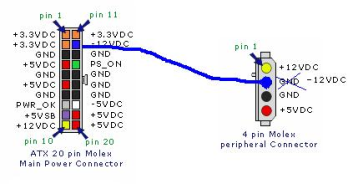
Power Supply
For powering up the function generator, a PC ATX power supply unit was used, where all voltages are already available (+12V, -12V, +5V). The wiring is shown in the following image, taken from scienceprog.com
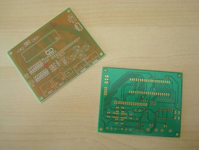
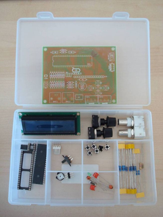
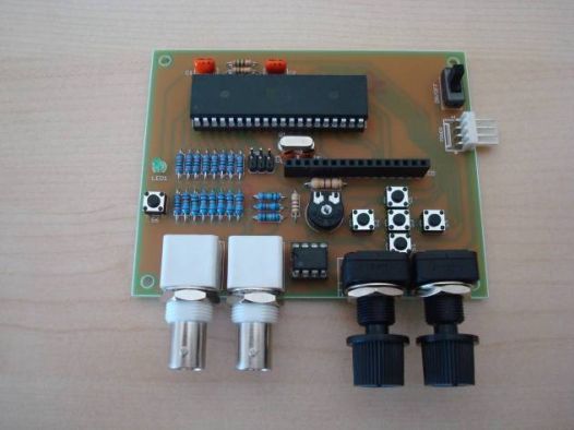
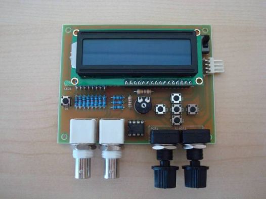
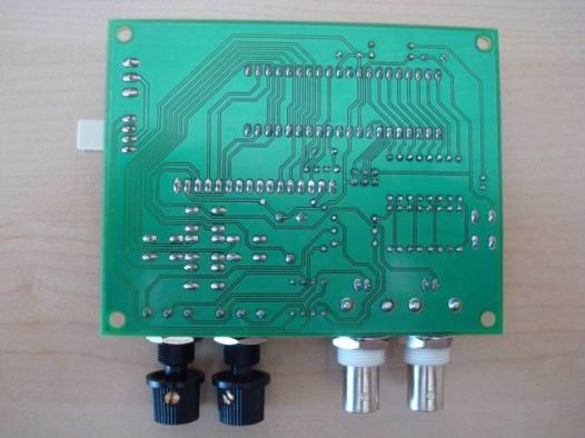
Photos of factory-made PCB and parts
Video
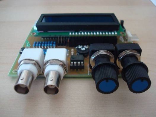
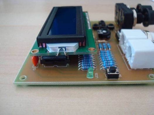
Photos of assembled PCB
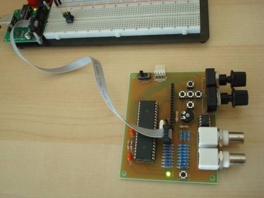
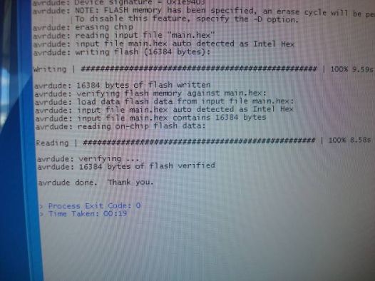
Programming of the ATMEGA16 with usbtiny programmer
The device firmware can be downloaded from :
http://www.scienceprog.com/avr-dds-signal-generator-v20
Changes in firmware
Because of the present LCD character orientation, which is different from the original implementation (180 degrees), the following changes in main.c were made :

Buttons LEFT and RIGHT were reversed :
#define LEFT 3//PORTD
#define RIGHT 1//PORTD
Buttons TOP and BOTTOM were reversed :
#define DOWN 4//PORTD
#define UP 0//PORTD
For the latest version of AVR-GCC compiler, the following changes should be made (according to Geoff comment on scienceprog.com) :
struct signal{
volatile uint8_t mode; //signal
volatile uint8_t fr1; //Frequency [0..7]
volatile uint8_t fr2; //Frequency [8..15]
volatile uint8_t fr3; //Frequency [16..31]
volatile uint32_t freq; //frequency value
volatile uint8_t flag; //if 0 generator is OFF, 1 is ON
volatile uint32_t acc; //accumulator
volatile uint8_t ON;
volatile uint8_t HSfreq; //high speed frequency [1...4Mhz]
volatile uint32_t deltafreq; //frequency step value
}SG;
The ATMEGA16 fuses should be :
HIGH = 0×59
LOW = 0xCF
This is interpreted to the following options checked (all others unchecked) :
OCDEN
SPIEN
BOOTSZ1
BOOTSZ2
SUT1
SUT0
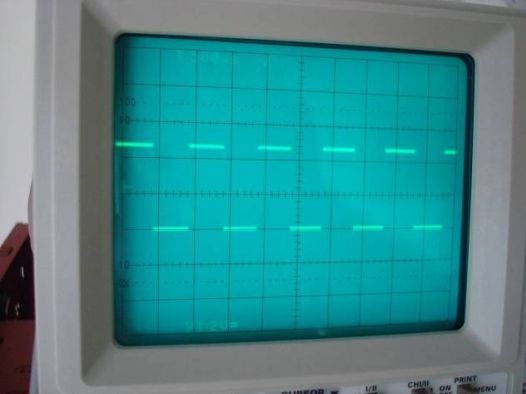
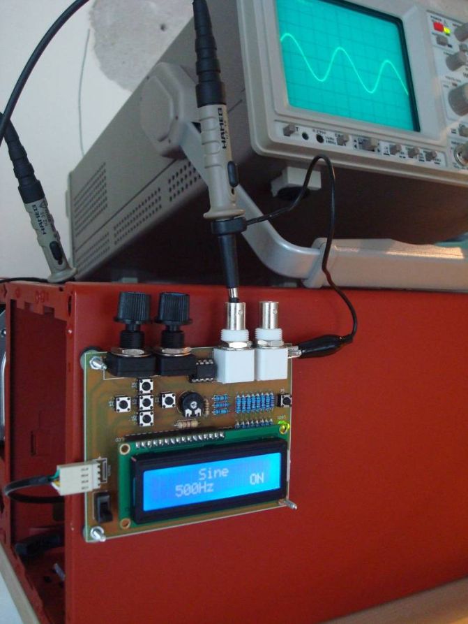
Photos of the device operation
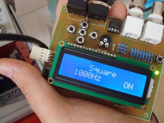
I just bought this on Ebay http://www.ebay.com/itm/1PC-DDS-Function-Signal-Generator-Module-Sine-Square-Sawtooth-Triangle-Wave-Kit-/251768575779?hash=item3a9e939723 which appears to be a fully built kit for sale, using the circuit described on this webpage. Unfortunately, the frequency output is half what it should be (1000Hz signal of any waveform setting gives me a 500Hz signal instead). Is this most likely something that was done wrong by the person who built the kit, or maybe in the firmware for the device has a glitch to start with? Would correcting it be as simple as adjusting the 10kohm trimmer resistor? Or would I need to reprogram the microcontroller to fix this issue? Any help with this would be great. Thanks in advance.
I bought the same board as you and unfortunately with the identical malfunction!
i could solve the problem 🙂 .. you have to reflash the controller because the fusebits are wrong. so i had dowloaded the firmware here: http://www.scienceprog.com/avr-dds-signal-generator-v20/, than i flashed ist with a usbtinyisp and avrdude. here the correct commands: avrdude -b 1200 -c usbtiny -p m16 -U flash:w:main.hex:i -U lfuse:w:0xcf:m -U hfuse:w:0x59:m
when i assembled my wingoon generator i was given 2 xtals one for16mhz and another for 8 mhz the silkscreen clearly indicate 16mhz. the other xtal was an 8mhz xtal wich if used would result in your issue
Hello, I have built this nice project based on your PCB design with some modifications to implement the the improvements from https://github.com/dev26th/avr_dds_20. First of all I want to thank everybody who was involved to develop this fantastic tool. My question is, I would like to rotate the display 180 degrees in the software, to make it easier for me to read it from the side where the potentiometers are located. Has anybody done this already? I am not a programmer and have no idea where to start, but as I am retired, I have the time to fight with this, if I get a hint in the right direction.
Of course I should do this when I made the PCB modification, but unfortunately I did not recognize that the display was on the other side. So hopefully someone can help:
HI , someone know how add a amplitude modulation for use as generator for repair am radio receiver ? i hope can added a external cicuit….
Thanks
Roberto