Programmable Step-Direction Pulse Generator for Stepper, BLDC and AC Servo Motor Drivers
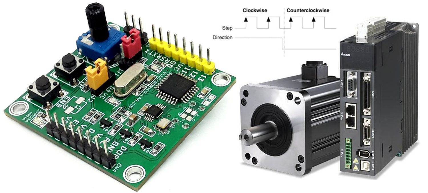
A programmable pulse generator is a very useful tool for stepper, BLDC, and AC servo drivers. Various stepper and servo drivers work with step and direction inputs.
A programmable pulse generator is a very useful tool for stepper, BLDC, and AC servo drivers. Various stepper and servo drivers work with step and direction inputs. This project is the right solution to drive such drivers since it can provide a high-frequency output which is important for most AC servo drivers. The project provides a jitter-free high-frequency pulse, direction, and enable signal. The output frequency can be configured up to 12 MHz since the project is Arduino-compatible. All outputs are open collector types (5V). 2 x tactile switches are provided to set the direction and enable. An onboard trimmer potentiometer is provided to adjust the step frequency.
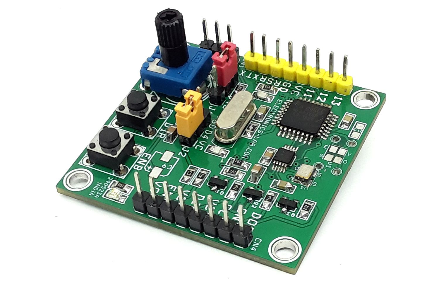
The project is Arduino compatible and consists, of an ATMEGA328 micro-controller, AD9833 DDS chip, tactile switches, and onboard trimmer pot. On-board connector provided for boot-loader and Arduino programming connector. 2 x Jumpers are connected to D3 and D4 pins of ATMEGA328. DDS chip can output high frequency up to 12Mhz.
Arduino Code
The Arduino code is available as a download below. Burn the bootloader and upload the code. The default output is 200Khz with this example code. The output frequency can be changed in Arduino code.
Arduino Pins: Digital Pin D3 and D4 Jumper J1 and J2, D9 = AD9833 FYNC, D11 = AD9833 SDATA, D13 = AD9833 SCLK
Features
- Supply 5V DC
- Current Consumption 30mA
- Output Frequency 200Khz (Range Up to 12Mhz) – Open Collector
- Pulse, Enable, Direction Outputs are Open Connector TTL Type
- Direct Output from AD9833 Square wave TTL, (Triangular Wave, Sine wave = 0.6V)
- On Board Enable Switch
- On Board Direction Switch
- On Board Power LED
- On Board Trimmer Potentiometer to Adjust the Frequency
- Jumpers to select the Triangular Wave, Sine Wave, Square Wave, Half Square Wave
- Optional Components for Hardware Acceleration/Deacceleration (Resistor R5, and Capacitor C9)
- PCB Dimensions 43.34 x 41.43 mm
- 4 x 3MM Mounting Holes
Frequency Generator
The board also can be used as a frequency generator. Jumpers J1 and J2 are provided to select the pulse type output. Use pin 8 of CN4 for direct output. Square output is TTL 5V, but tringle and sinewave output is lower.
Pulse Frequency
The default frequency output is 200Khz, this can be increased or decreased in Arduino code as per requirements. AD9833 supports frequencies up to 12Mhz. The output frequency is depended on the stepper driver micro-stepping setup and drive requirement; it is important to configure the required frequency in Arduino code.
Ramp
Example code doesn’t have the option to adjust the Acceleration and Deceleration. Users may include this in Arduino code. Little acceleration can be achieved with hardware changes. Install R5 10K to 100K, Install Capacitor C9 electrolytic value between 10uF to 33uF to include hardware acceleration.
Outputs
Step Pulse, Direction, and enable outputs are open collector type and TTL compatible, Direct Output of AD9833 (CN4 pin 8) is TTL for square wave and 0.6V Sinewave and Triangular Wave.
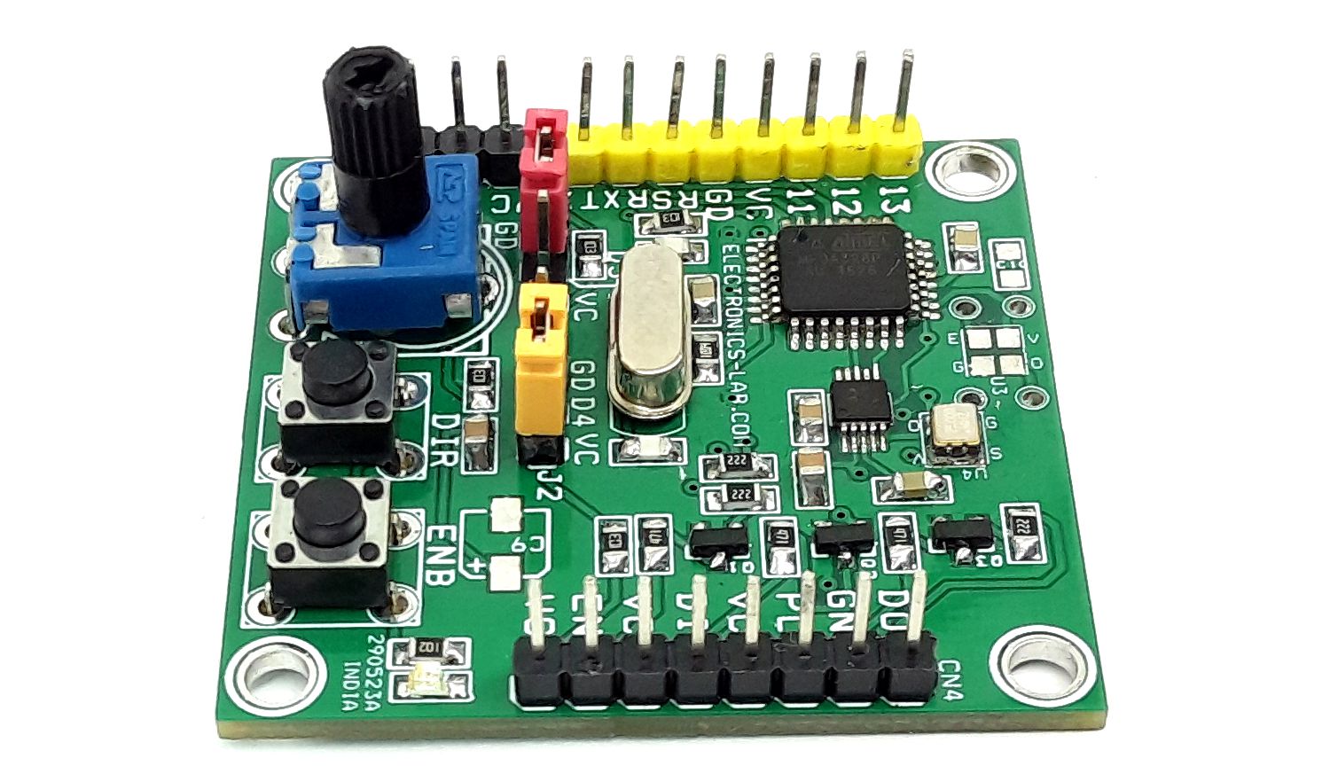
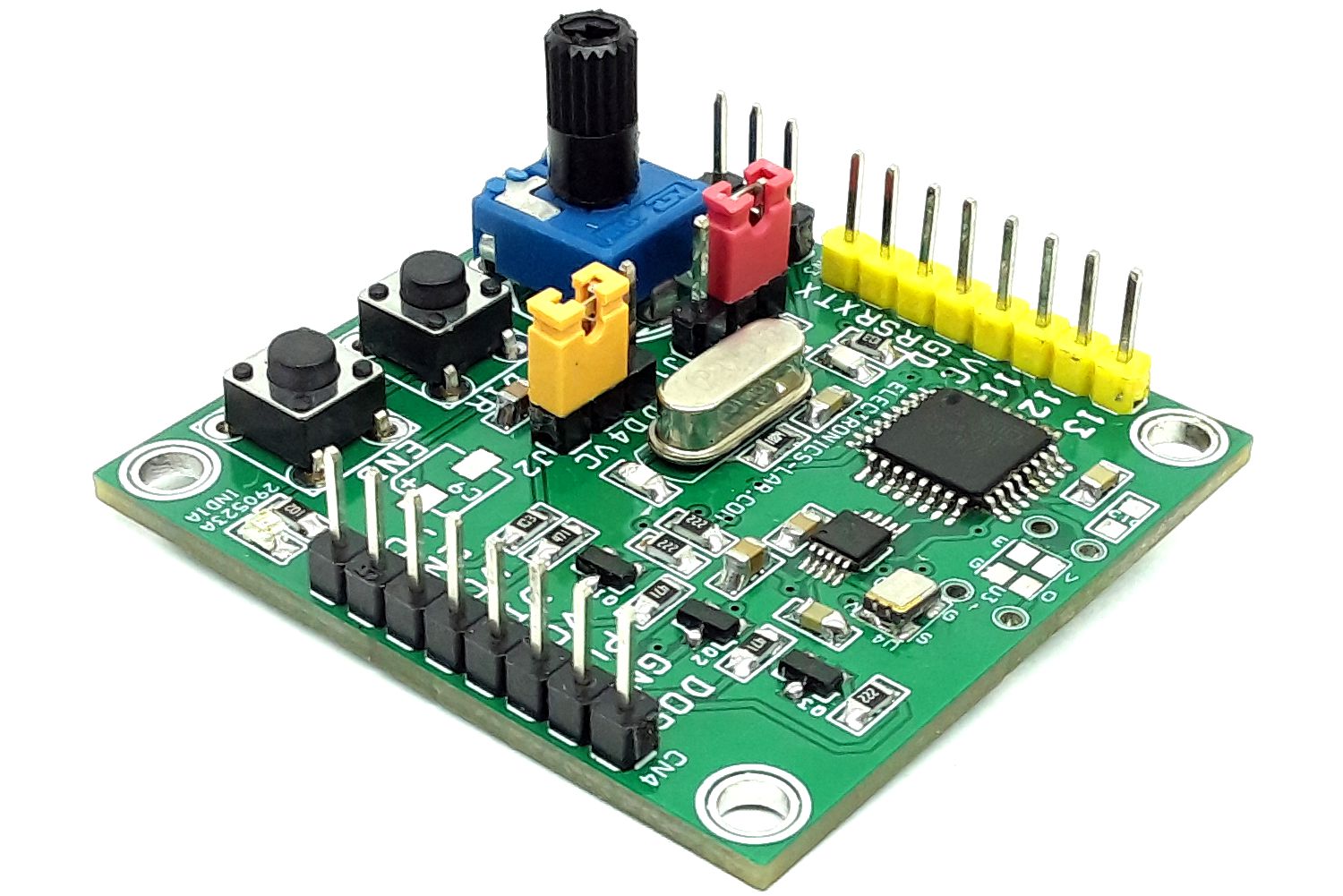
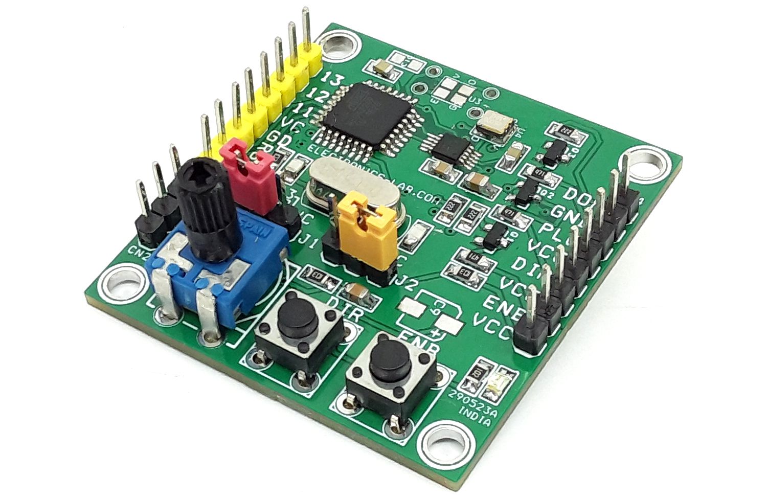
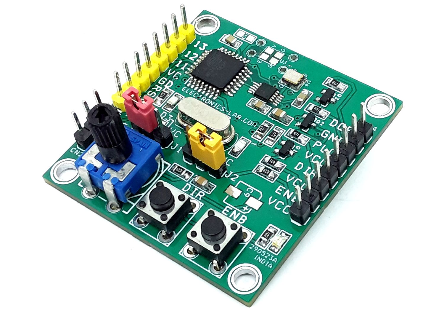
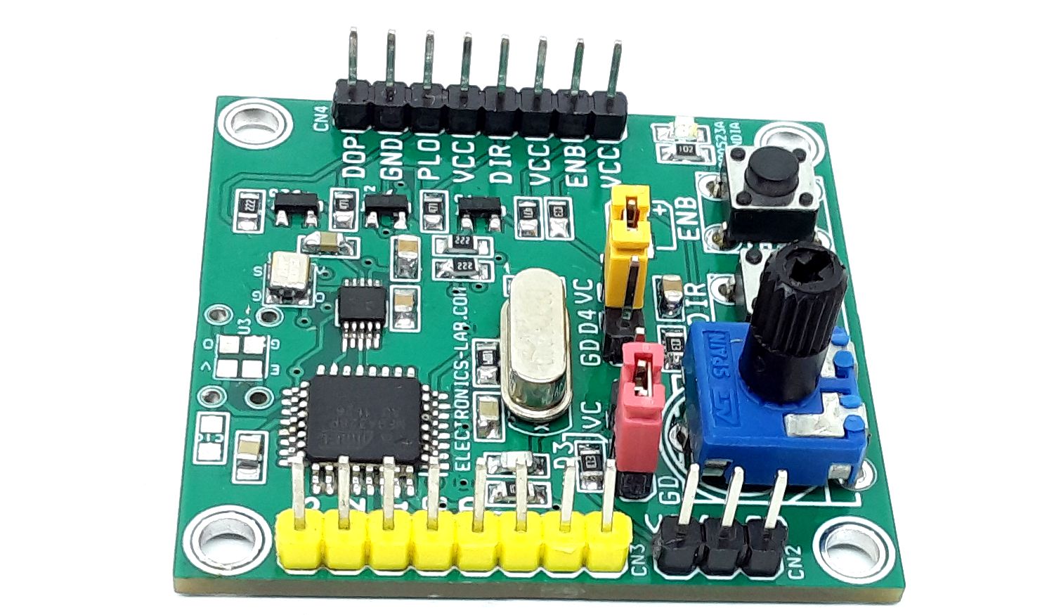
Connections and Other Details
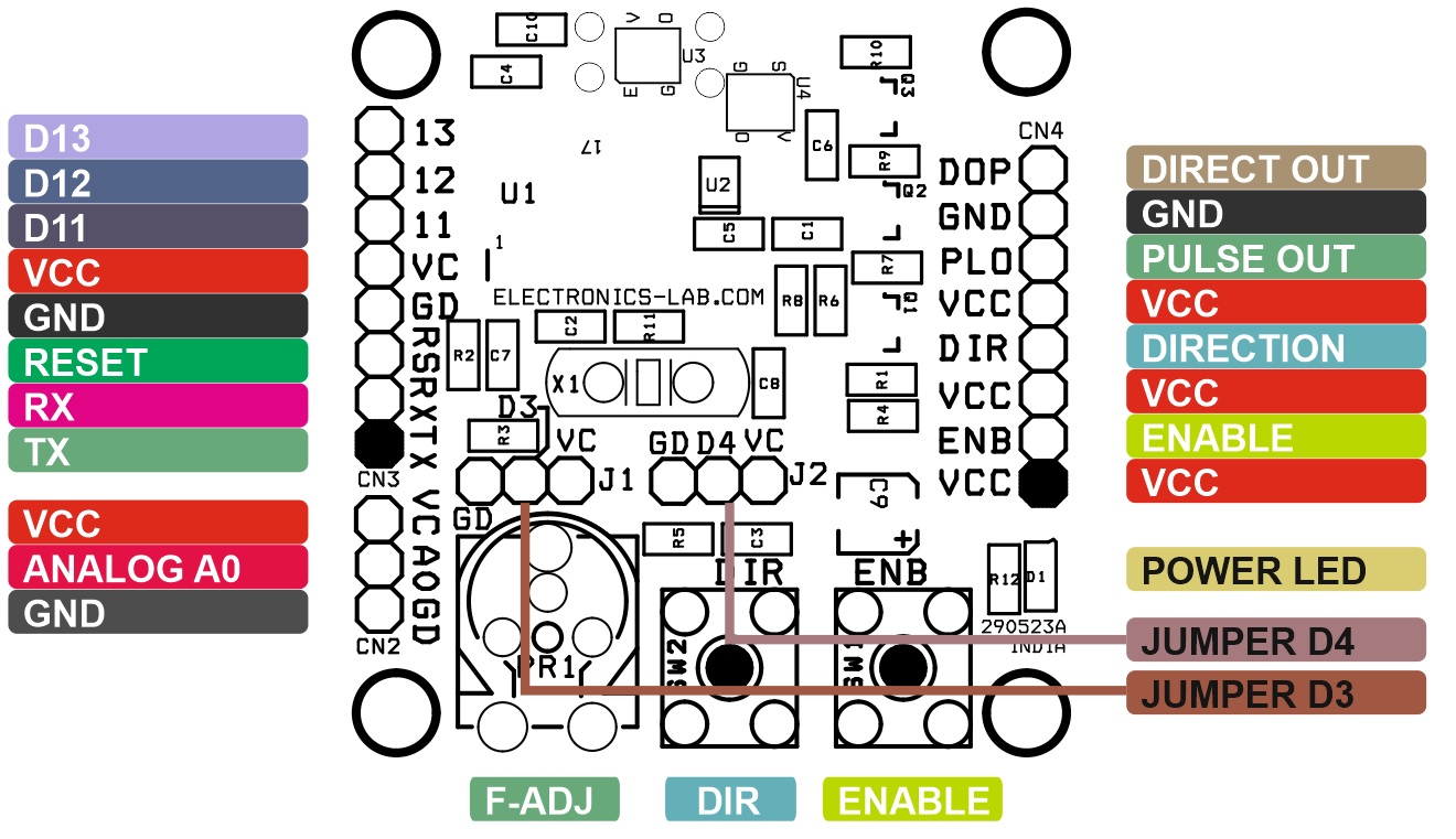
- CN1: Not Configured
- CN2: External Analog Input/External Potentiometer (In this case don’t install PR1)
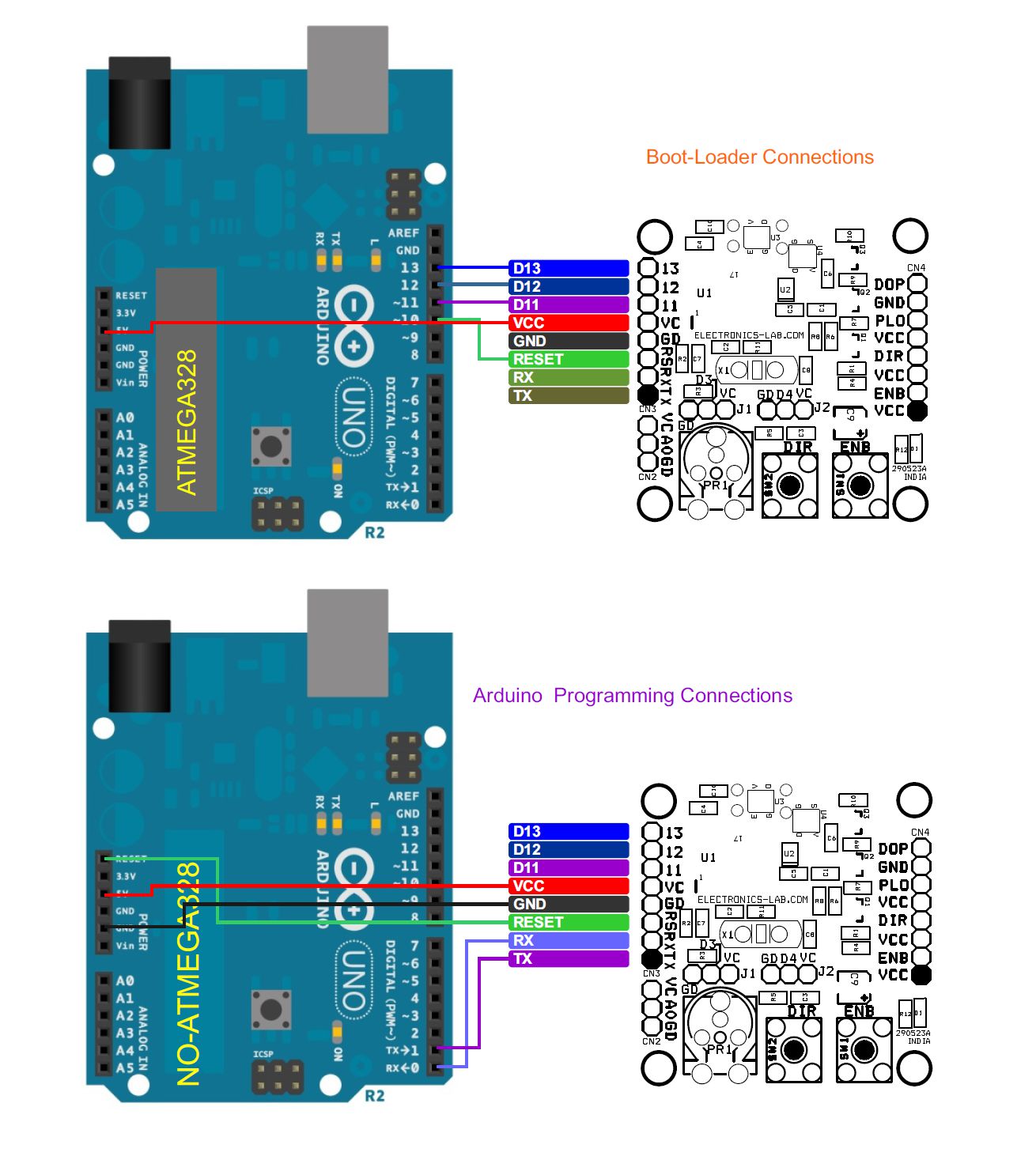
- CN3: Programming/Boot-Loader Pin 1 = TX, Pin 2 = RX, Pin 3 = Reset, Pin 4 = GND, Pin 5 = VCC, Pin 6 = D11, Pin 7 = D12, Pin 8 = D13
- CN4: Pin 1 =VCC, Pin 2 = Enable, Pin 3 = VCC, Pin 4 = Direction, Pin 5 = VCC, Pin 6 = Pulse Output, Pin 7 = GND, Pin 8 = Direct Pulse Output
- J1 and J2: Signal Output Selection / Optional Jumpers for Various Applications
- SW1: Enable
- SW2: Direction
- D1: Power LED
Frequency Generator Jumper Settings
- J1-D3 = 0(Low) , J2-D4 = 0 (Low) >> Sine Wave
- J1-D3 = 0(Low) , J2-D4 = 1 (High) >> Triangular Wave
- J1-D3 = 1(High) , J2-D4 = 0 (Low) >> Square Wave
- J1-D3 = 1(High) , J2-D4 = 1 (High) >> Half Square Wave
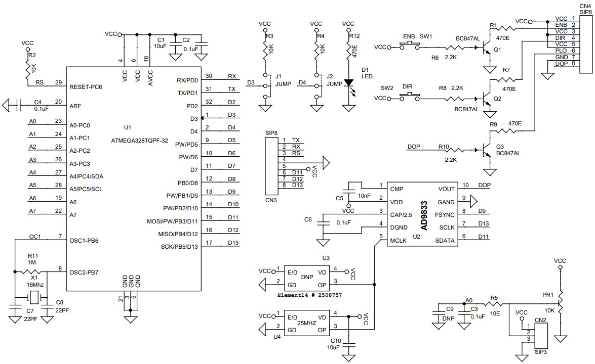
Schematic
Parts List
| NO. | QNTY. | REF. | DESC. | MANUFACTURER | SUPPLIER | SUPPLIER'S PART NO |
|---|---|---|---|---|---|---|
| 1 | 1 | CN2 | 3 PIN MALE HEADER PITCH 2.54MM | WURTH | DIGIKEY | 732-5316-ND |
| 2 | 2 | CN3,CN4 | 8 PIN MALE HEADER PITCH 2.54MM | WURTH | DIGIKEY | 732-5321-ND |
| 3 | 2 | C1,C10 | 10uF/10V CERAMIC SMD SIZE 0805 | YAGEO/MURATA | DIGIKEY | |
| 4 | 4 | C2,C3,C4,C6 | 0.1uF/50V CERAMIC SMD SIZE 0805 | YAGEO/MURATA | DIGIKEY | |
| 5 | 1 | C5 | 10nF/50V CERAMIC SMD SIZE 0805 | YAGEO/MURATA | DIGIKEY | |
| 6 | 2 | C7,C8 | 22PF/50V CERAMIC MSD SIZE 0805 | YAGEO/MURATA | DIGIKEY | |
| 7 | 2 | U3,C9 | DNP | |||
| 8 | 1 | D1 | LED RED SMD SIZE 0805 | LITE ON INC | DIGIKEY | 160-1427-1-ND |
| 9 | 2 | J1,J2 | 2 PIN MALE HEADER PITCH 2.54MM | WURTH | DIGIKEY | 732-5315-ND |
| 10 | 3 | R2,R3,R4 | 10K 5% SMD SIZE 0805 | YAGEO/MURATA | DIGIKEY | |
| 11 | 3 | Q1,Q2,Q3 | BC847AL SOT23 | DIODE INC | DIGIKEY | BC847BT-FDICT-ND |
| 12 | 4 | R1,R7,R9,R12 | 470E 5% SMD SIZE 0805 | YAGEO/MURATA | DIGIKEY | |
| 13 | 1 | R5 | 10E 5% SMD SIZE 0805 | YAGEO/MURATA | DIGIKEY | |
| 14 | 3 | R6,R8,R10 | 2.2K 5% SMD SIZE 0805 | YAGEO/MURATA | DIGIKEY | |
| 15 | 1 | R11 | 1M 5% SMD SIZE 0805 | YAGEO/MURATA | DIGIKEY | |
| 16 | 1 | SW1 | TACTILE SWITCH 4 PIN | NKK SWITCH | DIGIKEY | HP0215AFKP2-ND |
| 17 | 1 | SW2 | TACTILE SWITCH 4 PIN | NKK SWITCH | DIGIKEY | HP0215AFKP2-ND |
| 18 | 1 | U1 | ATMEGA328TQPF-32 | MICROCHIP | DIGIKEY | ATMEGA328PB-AURCT-ND |
| 19 | 1 | U2 | AD9833 | ANALOG DEVICE | DIGIKEY | 505-AD9833BRMZ-REEL7CT-ND |
| 20 | 1 | U4 | 25MHZ/3.2X2MM OSCILATOR 5V | ALIEXPRES | DIGIKEY | ALIEXPRESS |
| 21 | 1 | X1 | 16Mhz | ECS INC | DIGIKEY | X1103-ND |
| 22 | 1 | PR1 | 10K TRIMMER POT | PIHER | DIGIKEY | 1993-1104-ND |
| 23 | 2 | J1,J2 | SHUNT | SULLINS CONCT | DIGIKEY | S9001-ND |
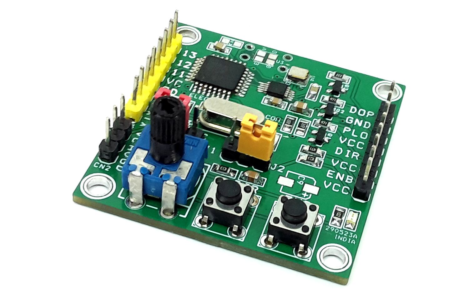
Connections
Gerber View
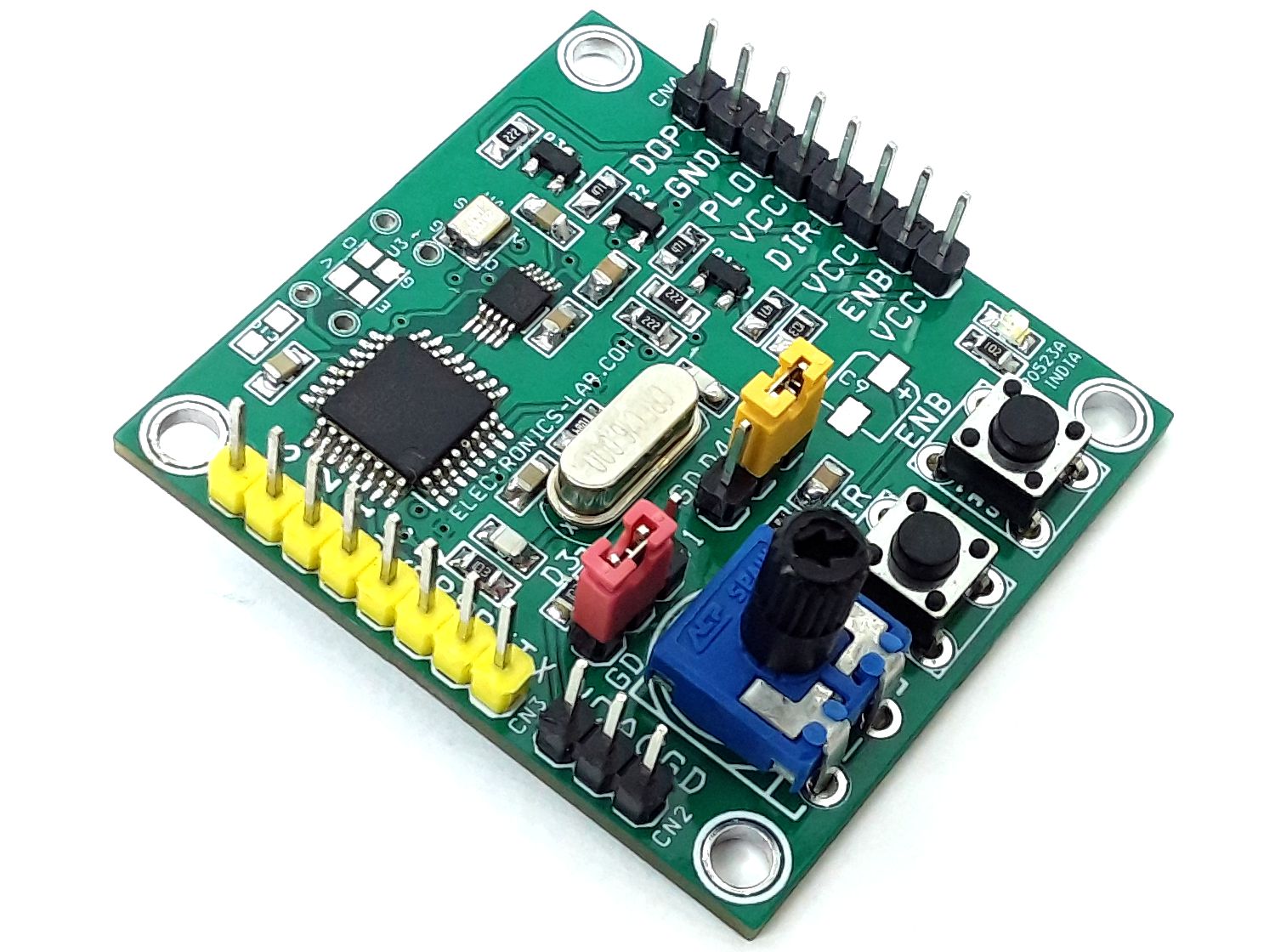
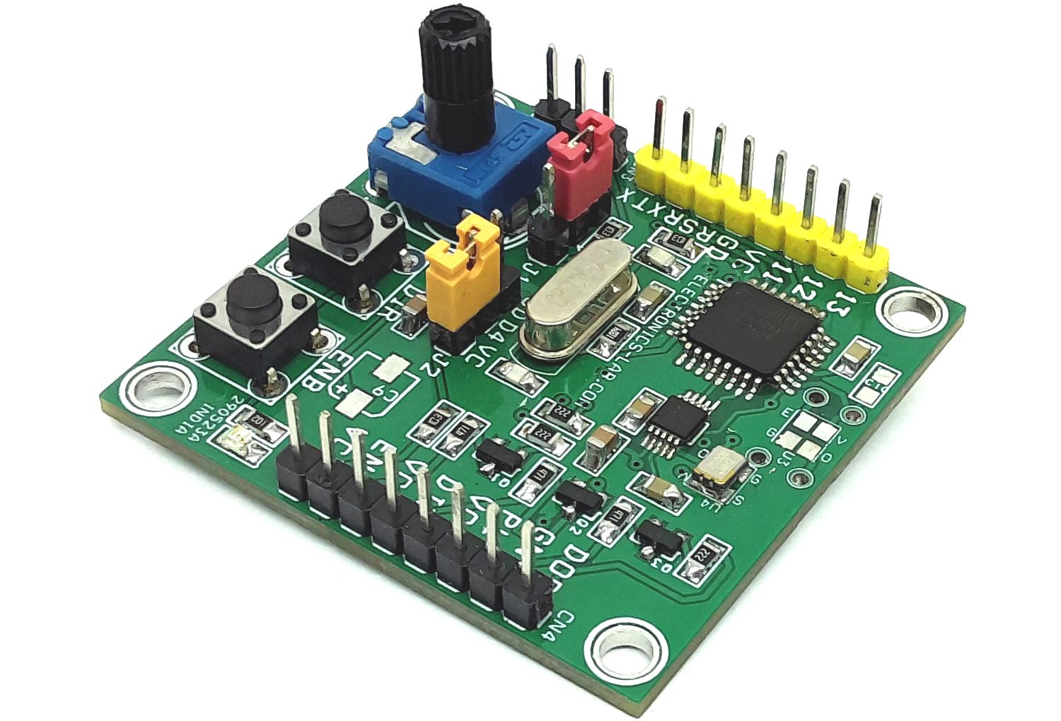
Photos
Video