

How to drive Nokia 5110 84×48 LCD display with Arduino
- Nick Koumaris
- https://educ8s.tv
- info@educ8s.tv
- 27.003 Views
- moderate
- Tested
- 0 Likes

Introduction
In the previous tutorial I showed how to build a weather station using DHT11 and BMP180 with an Arduino. However, the project has a downside which is the power consumption of the 16X2 LCD. If we were building a battery powered project with the desire to last for several weeks and probably several months, like a weather station for instance, then we’ll have to replace the LCD keypad shield from the previous tutorials and go for something like the low powered Nokia 5110 84×84 LCD display. In this tutorial I will be showing you how to drive this display with the Arduino and thus build projects with longer battery life.
Project parts
Since we are just going to drive the display we won’t be needing sensors for this tutorial, however we will need the components listed below which include the Nokia 5110 itself and we will show how to drive the display using an Arduino board.
1. Nokia 5110 84×84 LCD
2. Arduino Mega
3. Jumpers
4. Breadboard
5. Power bank
The Nokia 5110 display is basically a graphic LCD display useful for a lot of applications. It was intended originally to be used as a screen for cell phones and was used in lots of mobile phones during the 90’s. This display uses a low powered CMOS LCD controller/driver PCD8544, which drives the graphic display of size 84×48. It is very cheap and costs about 3$. You can get one here.
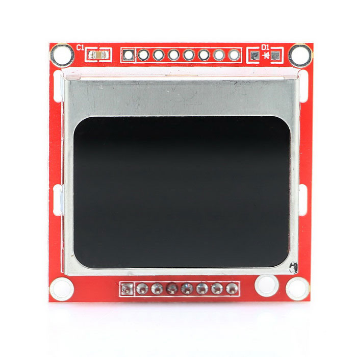
The Nokia 5110 LCD can display text, graphics as well as bitmaps. When this display is fully lit, it draws about 10mA but with the backlight off, it draws as low as 0.4mA. The power consumed by this display is very low compared to that of the keypad LCD shield used in the previous tutorial. I will be using the Arduino Mega for this tutorial as usual and you can buy one here. You can also buy jumpers, breadboards and power bank which you will be needing for this tutorial.
With the components acquired (links attached to the list), let’s wire them up.
Schematic
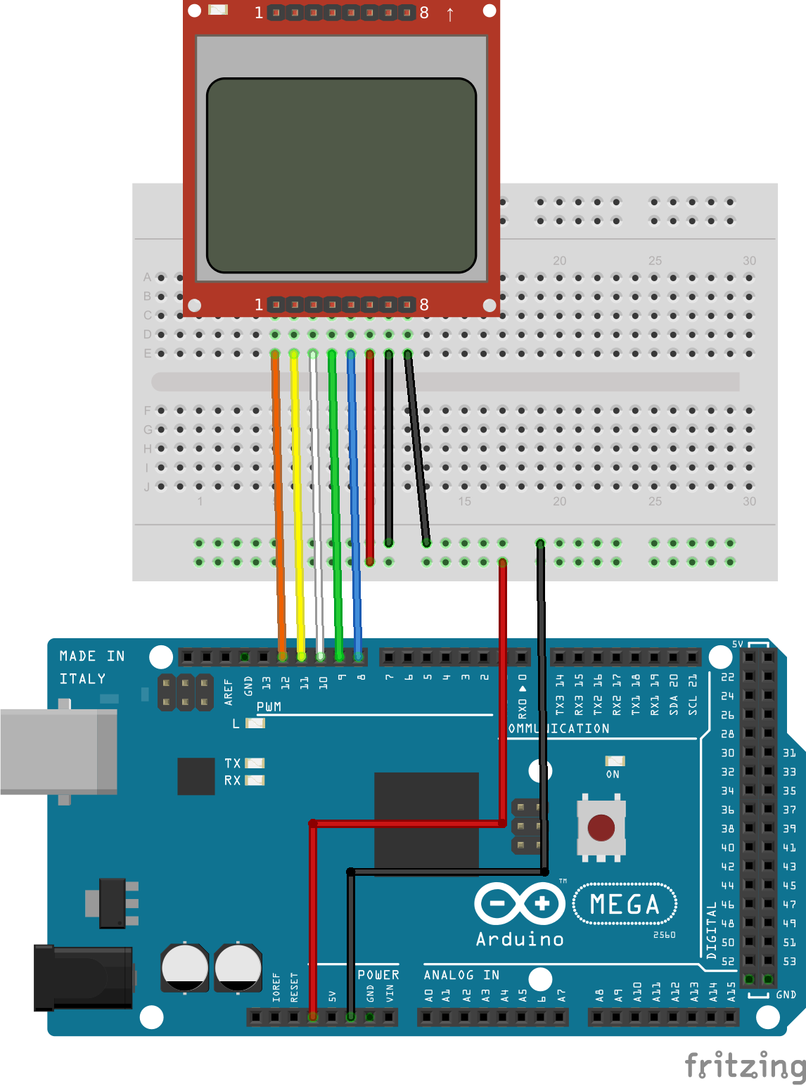
The display has two sides to which headers pins can be connected. You can pick one of the sides and solder header pins so that the display can fit firmly on the breadboard. The display works best when powered with 3.3 volts.
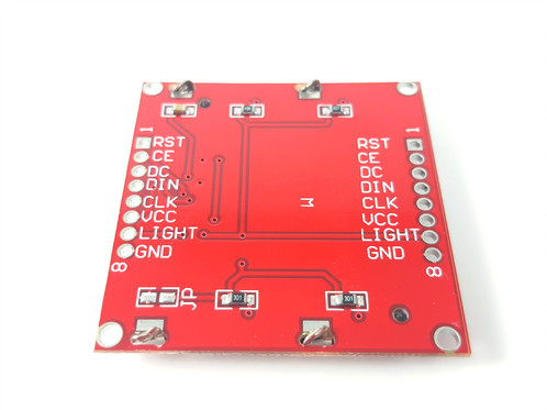
The light pin, when connected to ground turns the backlight “ON” while connecting it to VCC turns it “OFF”.
Nokia 5110 display connection
Display - Arduino
Pin 1(RST) – D12
Pin 2(CE) – D11
Pin 3(DC) – D10
Pin 4(DIN) – D9
Pin 5(CLK) – D8
Pin 6(VCC) - VCC
Pin 7(LIGHT) - GND
Pin 8(GND) - GND
Now that we are done with the schematic, let’s move to the code for this project.
Code
Before we start writing the code for this project, first we need to download the 5110 LCD graph library that was made by rinky-dink electronics. The library does most of the heavy lifting and makes it easy for us o use the LCD. Click here to visit the download page and then download the LCD5110_graph zip file. When done, unzip the file to your preferred location and then rename the unzipped folder to something simple like “LCD5110”. Copy and paste this folder in your arduino library folder, then run your arduino IDE.
Click on the file, then on examples and then click on LCD5110. Since we are using the Arduino Mega, under the LCD5110 drop down click on Arduino (AVR) and the open up the LCD graph demo file.
Lets break up the code into bits and explain.
// It is assumed that the LCD module is connected to
// the following pins using a levelshifter to get the
// correct voltage to the module.
//      SCK  - Pin 8
//      MOSI - Pin 9
//      DC   - Pin 10
//      RST  - Pin 11
//      CS   - Pin 12
//
In the code we only have to change a few things. we can see from the comment section above that the RST pin of the display was connected to pin 11 but in our case we connected this pin to pin 12 of the Arduino Mega. We also have to change the CS from pin 12 to 11.
The first line after the comment section, the LCD5110 library was included and after that a myGLCD object was created with the numbers being the pins to which the LCD is connected. The last two values in the myGLCD object is the RST and CS values which has been changed as explained initially.
#include <LCD5110_Graph.h>

LCD5110 myGLCD(8,9,10,12,11);
with this done, we move to the setup function. In the setup function, the InitLCD method is used to initialize the display and this method takes in a parameter for the display contrast. The contrast value is between 0-127 and since we didn’t pass in any value the default value which is 70 will be used. Next, the setFont method is called which sets smallFont as the display font style is called and lastly, the randomSeed function which is used to initialize the random number generator using analogRead on an unconnected pin as a random input.
void setup()
{
  myGLCD.InitLCD();
  myGLCD.setFont(SmallFont);
  randomSeed(analogRead(7));
}
In the loop function, on the first line the screen buffer is cleared using the clrScr method. The drawBitmap method was used to draw the arduino logo and this logo is placed in the screen buffer when the method is called. The update method is used to copy the screen buffer to the screen then we give it a delay of 2 seconds before clearing the screen buffer again.
myGLCD.clrScr();
  myGLCD.drawBitmap(0, 0, arduino_logo, 84, 48);
  myGLCD.update();

  delay(2000);

  myGLCD.clrScr();
  myGLCD.print("LCD5110_Graph", CENTER, 0);
  myGLCD.print("DEMO", CENTER, 20);
Next, a rectangle is drawn using the drawRect method. Lines are drawn in the for loop using the drawLine method which takes in four parameters (x1, y1, x2, y2). The font is changed to tiny font, then we print text on the screen and the update method is called to copy what’s in the string buffer to the screen. A delay of 5 seconds before clearing the screen is inserted.
Most of the functions used in the project have names that are self-explanatory like myGLCD.drawLine needs no explanation for instance as its clear the function draws a line.
myGLCD.drawRect(28, 18, 56, 28);
  for (int i=0; i<6; i++)
  {
    myGLCD.drawLine(57, 18+(i*2), 83-(i*3), 18+(i*2));
    myGLCD.drawLine((i*3), 28-(i*2), 28, 28-(i*2));
  }
  myGLCD.setFont(TinyFont);
  myGLCD.print("(C)2015 by", CENTER, 36);
  myGLCD.print("Henning Karlsen", CENTER, 42);
  myGLCD.update();

  delay(5000);

  myGLCD.clrScr();
Here is the full code for this project. Its an example from the Library named LCD5110_Graph_Demo and how to get to it has been described at the beginning of this section.
// LCD5110_Graph_Demo
// Copyright (C)2015 Rinky-Dink Electronics, Henning Karlsen. All right reserved
// web: http://www.RinkyDinkElectronics.com/
//
// This program is a demo of most of the functions
// in the library.
//
// This program requires a Nokia 5110 LCD module.
//
// It is assumed that the LCD module is connected to
// the following pins using a levelshifter to get the
// correct voltage to the module.
//      SCK  - Pin 8
//      MOSI - Pin 9
//      DC   - Pin 10
//      RST  - Pin 11
//      CS   - Pin 12
//
#include <LCD5110_Graph.h>

LCD5110 myGLCD(8,9,10,12,11);

extern uint8_t SmallFont[];
extern uint8_t arduino_logo[];
extern unsigned char TinyFont[];
extern uint8_t The_End[];
extern uint8_t pacman1[];
extern uint8_t pacman2[];
extern uint8_t pacman3[];
extern uint8_t pill[];

float y;
uint8_t* bm;
int pacy;

void setup()
{
  myGLCD.InitLCD();
  myGLCD.setFont(SmallFont);
  randomSeed(analogRead(7));
}

void loop()
{
  myGLCD.clrScr();
  myGLCD.drawBitmap(0, 0, arduino_logo, 84, 48);
  myGLCD.update();

  delay(2000);

  myGLCD.clrScr();
  myGLCD.print("LCD5110_Graph", CENTER, 0);
  myGLCD.print("DEMO", CENTER, 20);
  myGLCD.drawRect(28, 18, 56, 28);
  for (int i=0; i<6; i++)
  {
    myGLCD.drawLine(57, 18+(i*2), 83-(i*3), 18+(i*2));
    myGLCD.drawLine((i*3), 28-(i*2), 28, 28-(i*2));
  }
  myGLCD.setFont(TinyFont);
  myGLCD.print("(C)2015 by", CENTER, 36);
  myGLCD.print("Henning Karlsen", CENTER, 42);
  myGLCD.update();

  delay(5000);

  myGLCD.clrScr();
  for (int i=0; i<48; i+=2)
  {
    myGLCD.drawLine(0, i, 83, 47-i);
    myGLCD.update();
  }
  for (int i=83; i>=0; i-=2)
  {
    myGLCD.drawLine(i, 0, 83-i, 47);
    myGLCD.update();
  }

  delay(2000);

  myGLCD.clrScr();
  myGLCD.drawRect(0, 0, 83, 47);
  for (int i=0; i<48; i+=4)
  {
    myGLCD.drawLine(0, i, i*1.75, 47);
    myGLCD.update();
  }
  for (int i=0; i<48; i+=4)
  {
    myGLCD.drawLine(83, 47-i, 83-(i*1.75), 0);
    myGLCD.update();
  }

  delay(2000);

  myGLCD.clrScr();
  for (int i=0; i<8; i++)
  {
    myGLCD.drawRoundRect(i*3, i*3, 83-(i*3), 47-(i*3));
    myGLCD.update();
  }

  delay(2000);

  myGLCD.clrScr();
  for (int i=0; i<17; i++)
  {
    myGLCD.drawCircle(41, 23, i*3);
    myGLCD.update();
  }

  delay(2000);

  myGLCD.clrScr();
  myGLCD.drawRect(0, 0, 83, 47);
  myGLCD.drawLine(0, 23, 84, 23);
  myGLCD.drawLine(41, 0, 41, 47);
  for (int c=0; c<4; c++)
  {
    for (int i=0; i<84; i++)
    {
      y=i*0.017453292519943295769236907684886;
      myGLCD.invPixel(i, (sin(y*6)*20)+23);
      myGLCD.update();
      delay(20);
    }
  }

  delay(2000);

  for (int pc=0; pc<3; pc++)
  {
    pacy=random(0, 28);

    for (int i=-20; i<84; i++)
    {
      myGLCD.clrScr();
      for (int p=4; p>((i+20)/20); p--)
        myGLCD.drawBitmap(p*20-8, pacy+7, pill, 5, 5);
      switch(((i+20)/3) % 4)
      {
        case 0: bm=pacman1;
                break;
        case 1: bm=pacman2;
                break;
        case 2: bm=pacman3;
                break;
        case 3: bm=pacman2;
                break;
      }
      myGLCD.drawBitmap(i, pacy, bm, 20, 20);
      myGLCD.update();
      delay(25);
    }
  }

  for (int i=0; i<25; i++)
  {
    myGLCD.clrScr();
    myGLCD.drawBitmap(0, i-24, The_End, 84, 24);
    myGLCD.update();
    delay(100);
  }
  myGLCD.setFont(SmallFont);
  myGLCD.print("Runtime (ms):", CENTER, 32);
  myGLCD.printNumI(millis(), CENTER, 40);
  myGLCD.update();
  for (int i=0; i<5; i++)
  {
    myGLCD.invert(true);
    delay(1000);
    myGLCD.invert(false);
    delay(1000);
  }
}
Connect the board to your PC and make sure the right board and COM port are chosen. This can be done under the tools menu then Click on upload.
Demo
After uploading the code, you should see an output like the one shown in the image below.
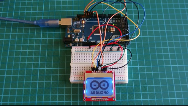
Worked right? Yay!!!
See you next time. Don’t forget to leave your comments and questions.
The code is an example for the library so probably no need to attach here again.
You can watch a video tutorial of this topic here on youtube


Who need make characters for LCD nokia is this web easy way- http://ilo.php5.sk/lcd84x48.htm
You can generate code for PIC16f84 or binary or array code for PIC,MPLAB XC8(Arduino)