Using a Hall Effect Sensor with Arduino
Hi guys, welcome to today's tutorial. Today we will look at how to use a hall effect sensor with Arduino.
Hi guys, welcome to today’s tutorial. Today we will look at how to use a hall effect sensor with Arduino.
A hall effect sensor is a sensor that varies its output based on the presence or absence of a magnetic field. This means that the output signal produced by a Hall effect sensor is a function of magnetic field density around it. When the magnetic flux density around it exceeds a certain pre-set threshold value, the sensor detects it and generates an output voltage sometimes called the hall voltage to indicate the presence of the magnetic field.
Hall sensors are becoming very popular due to their versatility and they are used in many different applications. One of the popular applications of hall effect sensors is in automotive systems where they are used to detect position, measure distance and speed. They are also used in modern devices like smartphones and computers and also used in different type of switches where the presence of a magnetic field is used to either activate or deactivate a circuit.
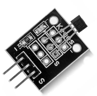
Hall sensors produce either analog or digital output depending on the particular sensor. Whichever type, they usually come in a three pin package with one pin to represent signal and the other two to provide power to the sensor. This makes easy the connection to any microcontroller.
For today’s tutorial, we will demonstrate how the hall effect sensor works by connecting it alongside a LED to an Arduino. The Arduino will be programmed such that when a magnet is brought close to the hall effect sensor, the LED comes on and when the magnet is removed, it goes off.
Required Components
The following components are required to build this project.
As usual, the exact components used for this tutorial can be bought via the links attached to each of the components listed above.
Schematics
The schematic for this project is a simple one, as all we have to do is connect the three pins of the hall sensor and an LED to the Arduino. Connect the components as shown in the schematics below.
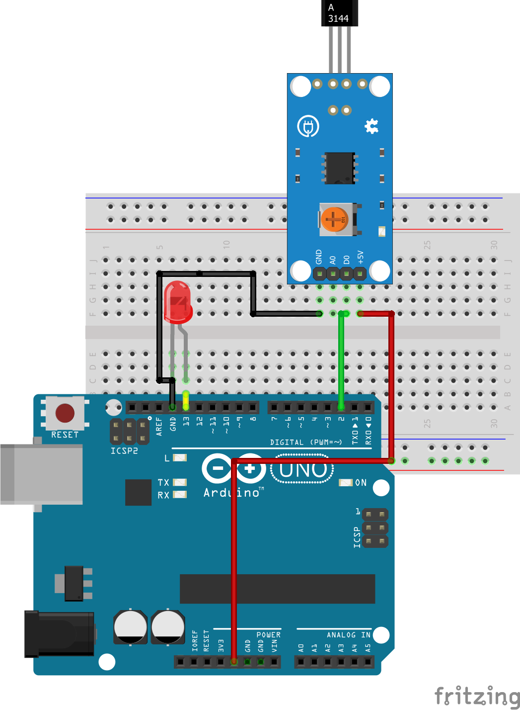
The connection is further described below to make it easy to follow.
Hall Sensor – Arduino
VCC - 5V
GND - GND
SIG - D2
The LED can be plugged directly into the Arduino with the positive leg in Arduino pin 13 and the other leg plugged into the ground pin without a resistor because arduino has an internal resistor attached to pin 13.
With the schematics done, we can proceed to the code for this project.
Code
The code for this project is really simple, all we want to do as earlier mentioned is to check if a magnetic field is being sensed and if yes, turn on the LED if no, we turn off the LED.
To do a short explanation of the code for this project, the first thing we do is declare the pins of the Arduino to which our hall sensor and LED is connected, after which we create a variable “state” which will store the value from the hall sensor.
   //////////////////////////////////////////////
  //        HALL EFFECT SENSOR DEMO           //
 //          Author: Nick Koumaris           //
//           http://www.educ8s.tv           //
/////////////////////////////////////////////

int hallSensorPin = 2;
int ledPin =  13;
int state = 0;
Next, we proceed to the void setup function where we declare the pin mode for the pins of the Arduino to which the LED and the Hall sensor are connected.
void setup() {
  pinMode(ledPin, OUTPUT);
  pinMode(hallSensorPin, INPUT);
}
Next is the void loop function, the task here is the same as if we want to use a push button to control an LED with an Arduino in between. We read the output of the hall sensor and store in a variable named state. When the value is LOW, we turn the LED, HIGH and when the value is high, we turn the LED Low. The configuration of your hall sensor may be different as the sensor may turn High when a magnetic field is detected. This should be confirmed on the sensor’s datasheet.
void loop(){

  state = digitalRead(hallSensorPin);

  if (state == LOW) {
    digitalWrite(ledPin, HIGH);
  }
  else {
    digitalWrite(ledPin, LOW);
  }
}
The complete code for this project is shown below and also available for download under the download section at the end of this tutorial.
   //////////////////////////////////////////////
  //        HALL EFFECT SENSOR DEMO           //
 //                                          //
//           http://www.educ8s.tv           //
/////////////////////////////////////////////

int hallSensorPin = 2;
int ledPin =  13;
int state = 0;

void setup() {
  pinMode(ledPin, OUTPUT);
  pinMode(hallSensorPin, INPUT);
}

void loop(){

  state = digitalRead(hallSensorPin);

  if (state == LOW) {
    digitalWrite(ledPin, HIGH);
  }
  else {
    digitalWrite(ledPin, LOW);
  }
}
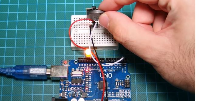
Demo
Copy the code and upload to your Arduino board. You should see the LED switch when a magnet is brought close to it as shown in the image below.
That’s it for this tutorial guys, thanks for following, If you have any questions as regards this tutorial, do not hesitate to drop it under the comment section of this tutorial. I will be glad to help.
The video version of this tutorial on youtube is here:
Till next time!
Helloo….. I want to measure strength of magnetic field using hall sensor…. I want to do this has my project….So will plz send the code….
In this project hall effect sensor is used as a detector of magnetic field to switch on and off a LED. For measuring the strength of a magnetic field you will need a completely different circuit.
Thank you very much for this tutorial! I tried it myself with the KY-024 Hall sensor. Here my result: https://nerd-corner.com/hallsensor-ky-024-arduino-code/