Using I2C SSD1306 OLED Display With Arduino
Introduction Sometimes it may be necessary to use a display when making a hardware project, but one confusing thing is the size of the display and the required pins to control it. This tutorial will show you how to use a small I2C OLED display with Arduino using only two wires.
Introduction
Sometimes it may be necessary to use a display when making a hardware project, but one confusing thing is the size of the display and the required pins to control it. This tutorial will show you how to use a small I2C OLED display with Arduino using only two wires.
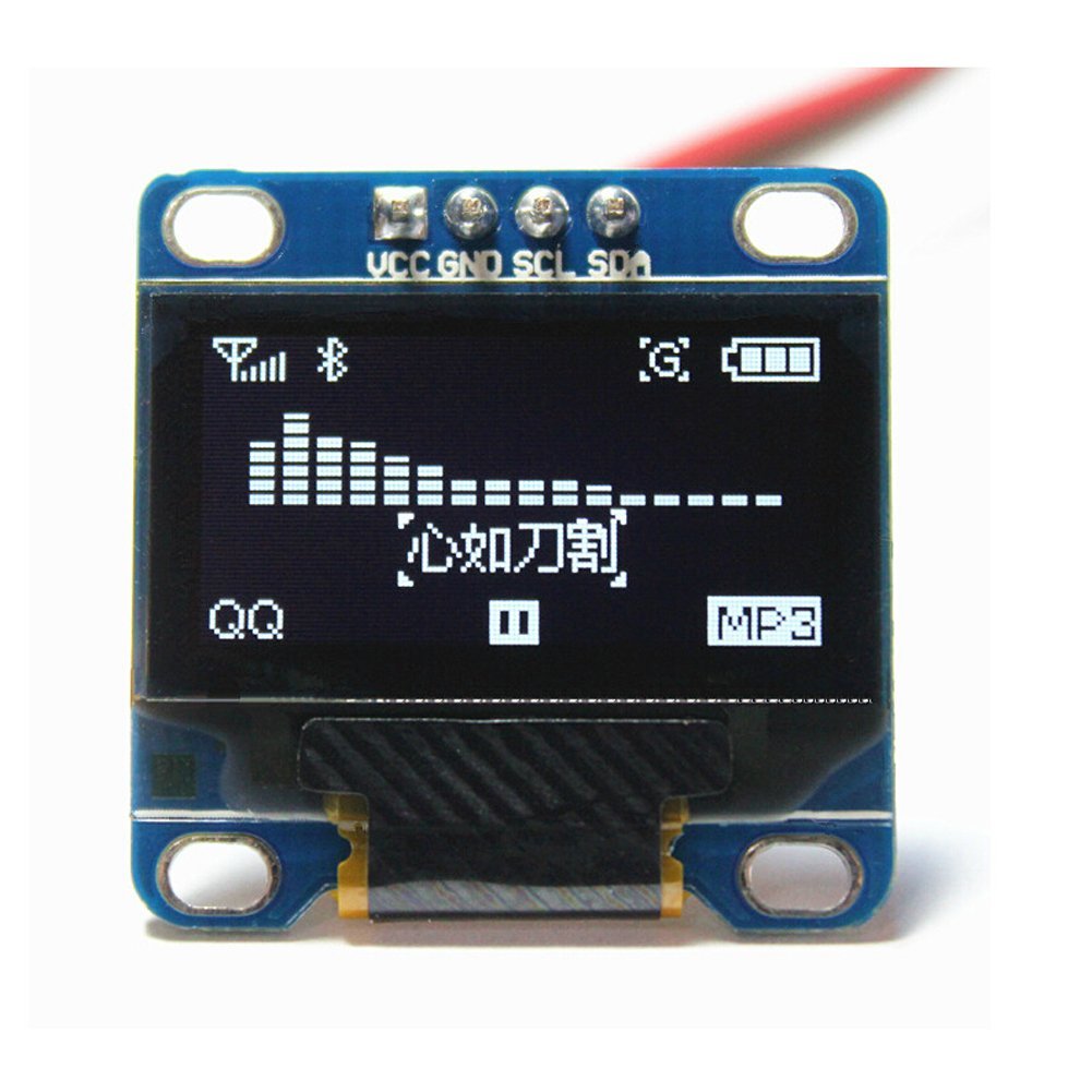
Geekcreit 0.96 Inch I2C OLED Display Module
The display used in this tutorial has a very small (2.7 x 2.8cm) OLED screen, that is similar to Arduino Pro Mini size, with 128 x 64 screen resolution. The OLED Driver IC is SSD1306, a single-chip CMOS OLED/PLED driver with controller for organic / polymer light emitting diode dot-matrix graphic display system. The module has only 4 pins, two of them are the supply pins, while the others are SCL and SDA, I2C protocol pins, which will be used to control the display.
This OLED display module is full compatible with Arduino and has an input voltage range between 3.3V and 6V and it need less than 10 mA current, so it can be connected with 3.3V or 5V pins. It is available on Banggood store for about $5.5.
Parts you will need
- The OLED Display
- An Arduino, (Arduino Mega in this tutorial)
- Power source, Powerbank, Battery, or USB cable.
- Wires.
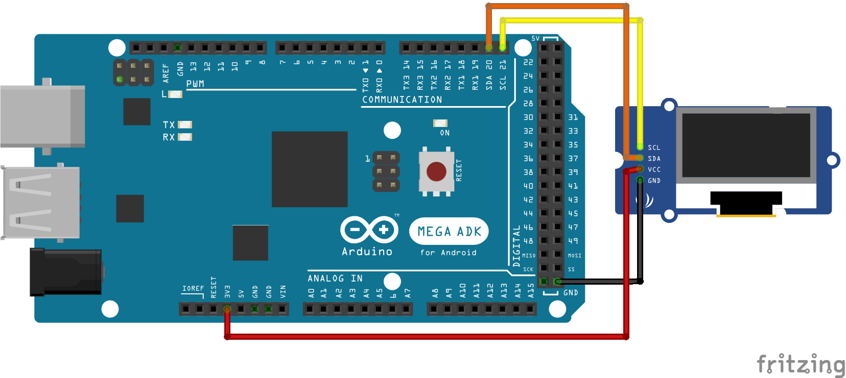
The Circuit
The circuit is very simple. First, connect the GND with Arduino GND, VCC with 3.3V or 5V on Arduino, SCL with SCL, and finally SDA with SDA pin. Upload the code and power on the Arduino.
I2C Protocol
The Inter-integrated Circuit (I2C) Protocol is a protocol intended to allow multiple slave digital integrated circuits to communicate with one or more master chips. It is only intended for short distance communications within a single device, and it only requires two signal wires to exchange information.
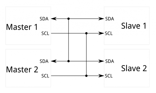
Each I2C bus consists of two signals: SCL and SDA. SCL is the clock signal, and SDA is the data signal. The clock signal is always generated by the current bus master. Messages are broken up into two types of frame: an address frame, where the master indicates the slave to which the message is being sent, and one or more data frames, which are 8-bit data messages passed from master to slave or vice versa. Data is placed on the SDA line after SCL goes low, and is sampled after the SCL line goes high.
The Code
First of all you need to download two libraries:
- Adafruit GFX library, this is the core graphics library, providing a common set of graphics primitives (points, lines, circles, etc.). It needs to be paired with a hardware-specific library.
- Adafruit SSD-1306 OLED display library, this is a library for the OLED displays based on SSD1306 drivers.
Unzip the two libraries and add them to the Arduino libraries folder, then run Arduino IDE and open the I2C exapmle from OLED library.
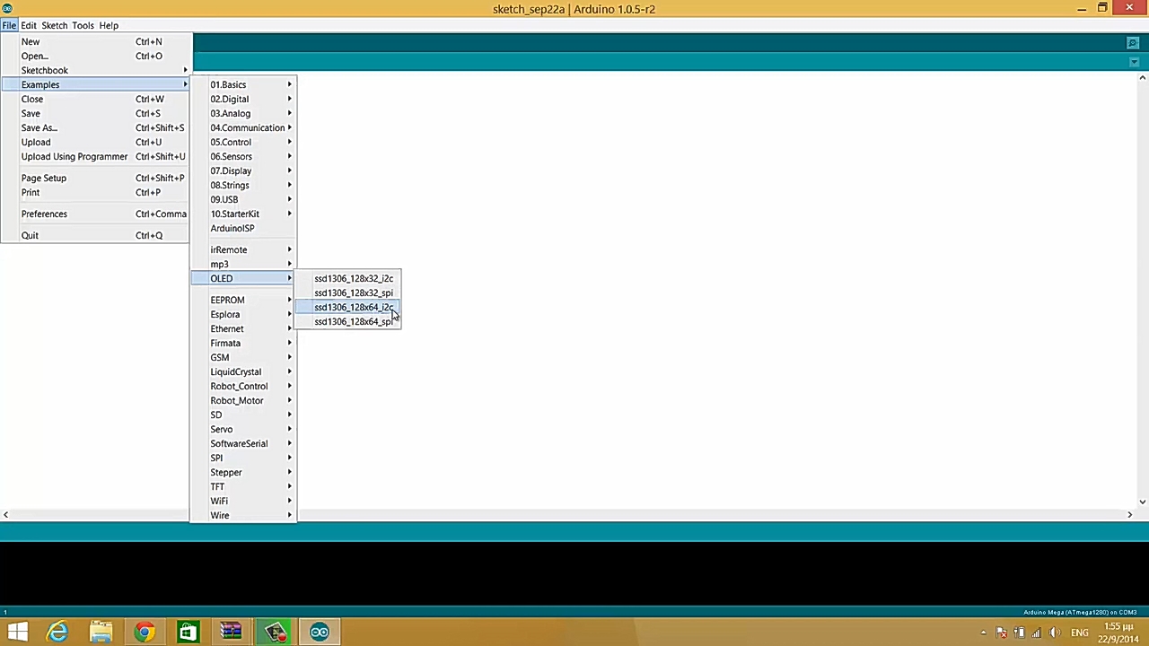
The only change you have to do is to change the I2C address of the display. Go to the setup function, and change the value on the display.begin function call from 0x3D to 0x3C. This is required because the 0x3D is the address of Adafruit OLED display, while the 0x3C is the address of the OLED display from Banggood.
After uploading the code to the Arduino, the screen will light up and start displaying lines, triangles, circles, and texts. You can use the function in the code to draw what you need.
This tutorial is made by educ8s.tv channel, and you can find the tutorial video below:
I would recommend to have a look at u8g2 lib from Oliver Kraus. Besides the old annoying “firstpage / nextpage” there is a faster (but more memory consuming) option to write directly to screen.
This lib supports a bunch of displays, runs on a lot of boards and uC, even with limited ressources…
Thanks for your positive input and suggestion!