6V Ultra-Bright LED Chaser
- Audioguru
- 22.723 Views
- moderate
- Tested
- 0 Likes

General
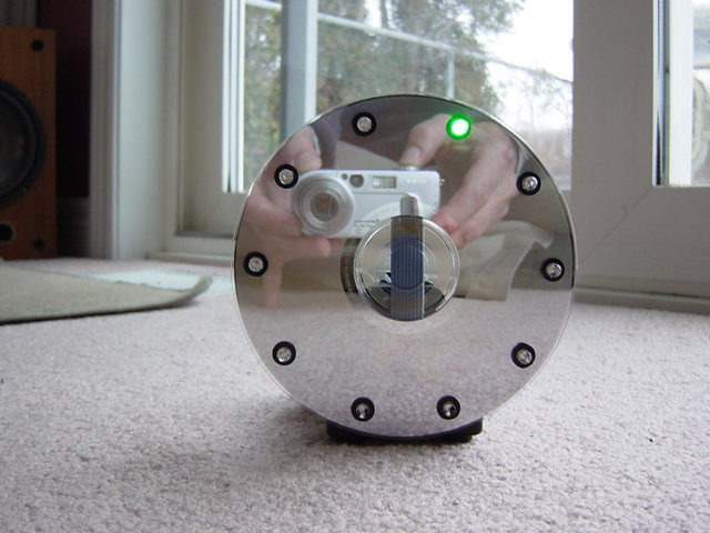
This is a spectacular but completely useless project. It lights Ultra-Bright LEDs in a sequence and each LED flashes brightly very briefly. The LEDs light-up going around and around since they are mounted in a circle (on a CD), then they pause before chasing again. The very brief flash of each LED (15ms) and the pauses (1 second) reduce the average current so the battery should last a long time.
For user convenience, this project has a stepper speed control and a brightness control. At slower speeds and/or reduced brightness, the batterys life is extended considerably.
At full brightness, the LEDs flash extremely brightly. More than one of this project grouped together occasionally synchronize, lighting the whole room for a moment.
Operation
At maximum speed, the LEDs dont appear to flash, instead they appear to move from one lighted one to the next, around and around. They rotate completely for 4 rotations in two seconds, and then turn off for a one second pause then repeat the sequence. At a lower speed, the number of rotations before the pause is less. It will do three rotations, two or even only one rotation at its slowest speed. A sequence of rotations starts with LED #2 and end with LED #9.
Specifications
Battery: Four AA alkaline cells.
Battery life:
- Minimum speed and brightness 2.3 years
- Medium speed and brightness 1 year
- Minimum speed, maximum brightness 4.1 months
- Maximum speed and brightness 3.8 weeks
Brightness: controlled with Pulse width Modulation, from off to extremely bright (4000mcd).
Stepper speed: 2 LEDs/sec to 2 revolutions/sec.
Pulse Width Modulation frequency: 3.9KHz.
LED current: 24mA pulses.
LED voltage drop: 3.2V at 24mA. Blue, green and white Ultra-Bright LEDs are suitable.
Minimum battery voltage:
- <3V, oscillators do not run.
- 3V, LEDs are very dim.
- 4V, LEDs reach almost full brightness.
Radio interference: none.
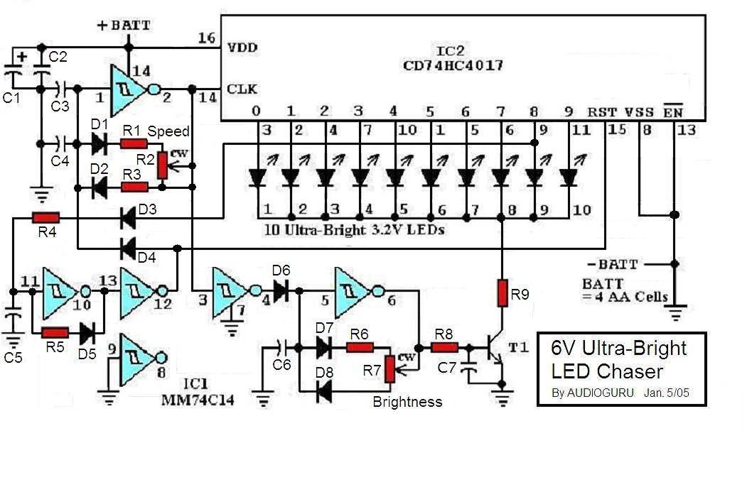
Circuit Description
- The CD74HC4017N high-speed Cmos IC is rated for a maximum supply voltage of 7V. It is rated for a maximum continuous output current of 25mA. In this project, the maximum supply voltage is 6.4V with brand new battery cells and the 24mA output current is so brief that the IC runs cool.
- The MC14584BCP* IC (Motorola) is an ordinary 4XXX series 3V to 18V Cmos IC, with a very low operating current and low output current. Its extremely high input resistance allows this project to use high value resistors for its timers and oscillators, for low supply current. Its 6 inverters are Schmitt triggers for simple oscillators and very quick switching.
- IC2 is a 10 stage Johnson counter/decoder. On the rising edge of each clock pulse its outputs step one-at-a-time in sequence. It drives the anode of each conducting LED toward the positive supply.
- IC1 pins 1 and 2 is a Schmitt trigger oscillator with C3 and C4 paralleled for a very low frequency. R1 and R2 control its frequency and the diodes with R3 combine with the capacitors to produce the 15mS on time for the LEDs.
- IC1 pins 5 and 6 is the brightness Pulse Width Modulation oscillator. The pot R7 with the associated diodes and resistors allow it to change the duty-cycle of its output for PWM brightness control. It drives the transistor.
- IC1 pins 3 and 4 is an inverter. It takes the low time (LEDs off) from the clock oscillator, inverts it to a high and shuts-off the brightness oscillator through diode D6.
- IC1 pins 11 and 10 is a sample-and-hold stage. It takes a sample of the pulse driving LED #9 though D3 and R4 and charges C5 in steps. At maximum speed it takes 4 steps for C5 to charge to the Schmitt switching threshold voltage. R5 and D5 slowly discharge C5 for the pause time.
- IC1 pins 13 and 12 is an inverter that resets the counter/decoder and shuts-off the clock oscillator through D4, during the pause time.
- IC1 pins 9 and 8 is not used and is shut-off by grounding its input.
- T1 is the PWM switching transistor. R9 limits the maximum LED current to 24mA.
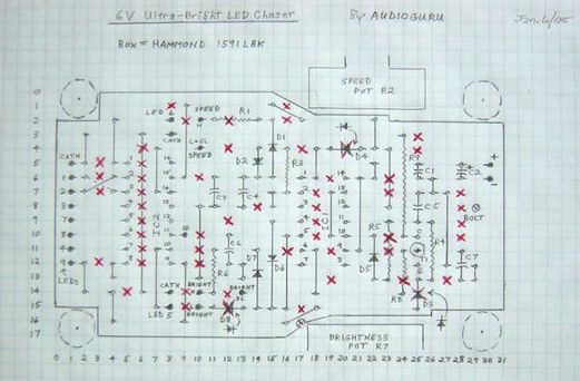
Construction
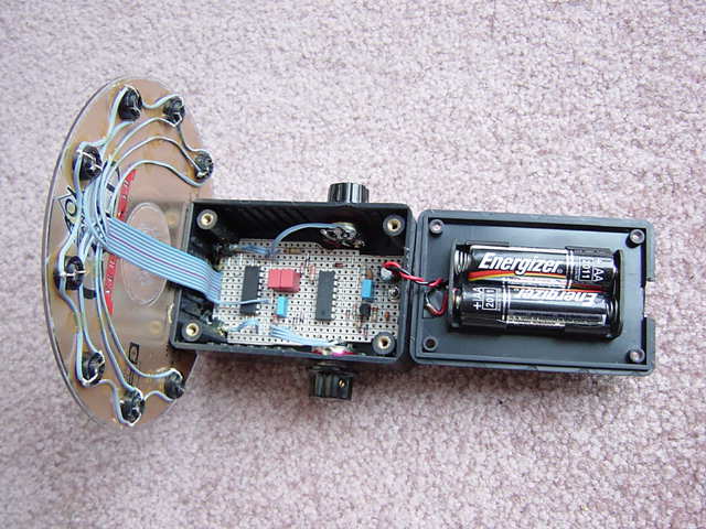
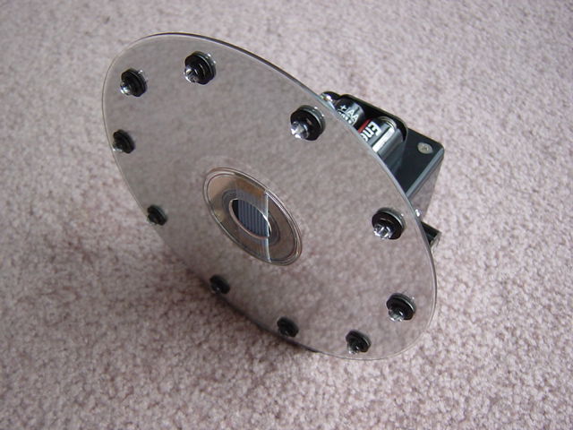
The 10 LEDs mount on a Compact-Disc which is glued to a plastic box with contact cement. The box houses the Veroboard circuit in its lower main part with the battery holders on its lid. Multiconductor ribbon cable joins the LEDs to the circuit. The pots mount on the sides of the box.
If you turn it down each night, its current is so low an on-off switch isnt needed.
Parts List
1 IC1 MC14584BCP (Motorola) * Ordinary Cmos hex Schmitt trigger inverters
1 IC2 CD74HC4017N High-speed Cmos decade counter/decoder
1 T1 2N3904 or 2N4401 NPN transistor
8 D1 to D8 1N4148 or 1N914 Diodes
10 LEDs Blue, green or white Ultra-Bright LEDs with Vf = 3.2V or less at 20mA
1 R1 100K 1/4W resistor
1 R2 1M Linear-taper potentiometer
1 R3 33K 1/4W resistor
1 R4 2.2M 1/4W resistor
1 R5 22M 1/4W resistor
1 R6 47K 1/4W resistor
1 R7 1M Audio-taper (logarithmic) potentiometer
1 R8 1.8K 1/4W resistor
1 R9 68 ohms 1/4W resistor
1 C1 100uF/16V Electrolytic capacitor
1 C2 0.1uF/50V Ceramic capacitor
2 C4 and C4 1uF/63V Metalized poly capacitor
1 C5 470nF Metalized poly capacitor
2 C6 and C7 1nF Metalized poly capacitor
* A CD74C14 can also be used for IC1 but R4 = 1M, R5 = 10M, C3 and C5 = 330nF, C4 = 470nF.
A 3V LED Chaser project also works well with these changed parts but using a CD74HC14N for IC1.
In addition to these changes, R8 = 680 ohms and R9 = 22 ohms. I built one using low-voltage (1.8V at 20mA) orange Ultra-Bright LEDs. The orange one looks good beside the green one.
Attachments: 6V LED Ultra-Bright Chaser schematic, Veroboard layout and 3 pictures.
I wish I knew how to take a slow picture with my sons digital camera, so all the LEDs would be lighted, and if I moved it would make nice lighted smears in the picture.
Photos