
OSCCAL Value Finder
- Rui Cabral
- http://www.ruijc.webnode.com
- rui.j.cabral@googlemail.com
- 12.131 Views
- moderate
- Tested
- 0 Likes

Introduction
When working with microcontrollers that require a factory calibrated osccal value stored in memory, its very normal that once in a while this setting could be lost during an upload of a new program or when accidentally erasing the device.
Im no exception and erased many times this value by mistake in several devices. Once this value is erased, its not possible to recover it unless it was written on a sheet of paper or in our own memory and use it to record it back.
This project has the ability to calculate what is the appropriate osccal value for the 12F675 microcontroller.
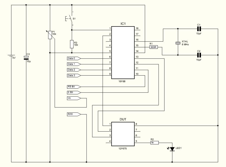
Schematic
Parts List
R1 300 ohms resistor
R2 1K ohms resistor
R3 10K ohms resistor
P1 10K Potentiometer
C1 15pF capacitor
C2 15pF capacitor
C3 10uF capacitor
Led1 3mm green led
LCD 8X2 LCD
XTAL 8Mhz cristal
IC1 16F88 microcontroller from Microchip
S1 Push button
Others:
Box
8 PIN IC SOCKET
PCB
Hex program for the microcontroller
How it works
The program loaded in the 12F675 device which has no osccal value will force a pulse on GPIO.4 and it will make a loop while increasing the osccal value internally.
GPIO.5 will send the current osccal value used for each pulse sent. Because the device has no calibrated osccal value, the pulse will be variable. The circuit will wait until it receives the correct pulse. When the correct pulse is received, it will stop the test and display the osccal value used when the correct pulse was measured.
The value displayed is in Hexadecimal format which means it can be used without conversions directly to the devices memory.
HEX Program
The Hex program named Oscfind1 must be saved in the 16F88 microcontrollers memory before soldering on the PCB.
The Hex program named Oscfind2 must be saved in the devices memory ( 12F675 ).
Testing
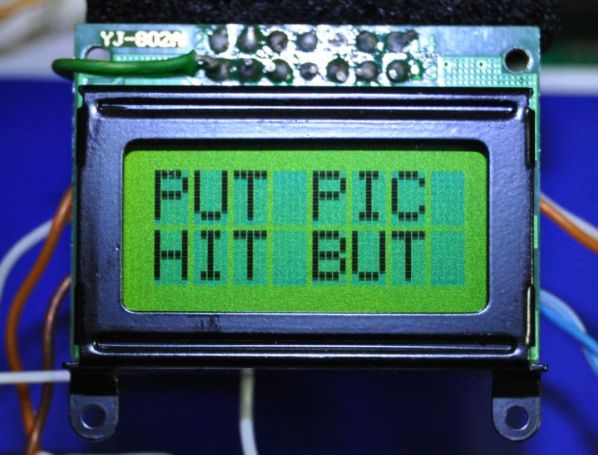
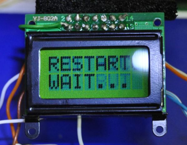
Turning on the circuit, it will display the name of the project and then it will display the message Put Pic Hit But . At this point its possible to place the 12F675 device on the socket and press the push button.
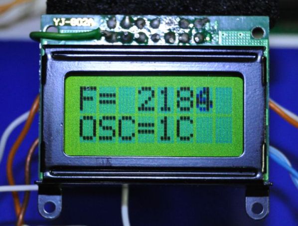
Pressing the push button S1 the circuit will start to measure the signal from the 12F675 device and will count the pulses. The display shows the pulse signal being measured and the current Osccal value.
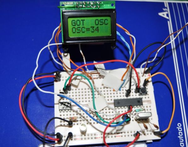
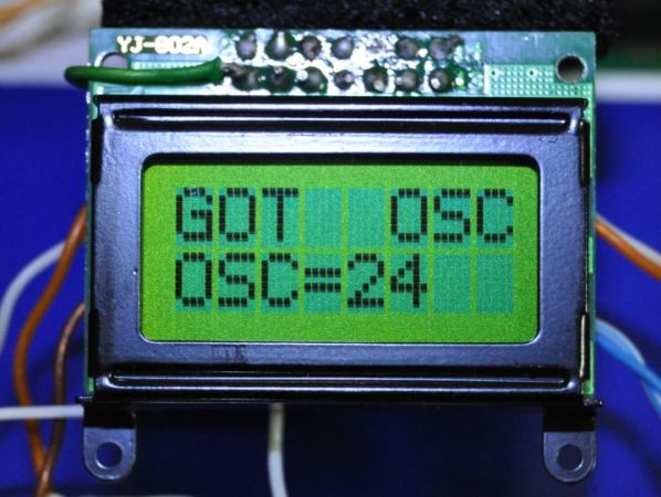
When the pulse sent by the 12F675 device matches the requested pulse length the circuit will stop the device and display the recommended osccal value.
Since the circuit controls the power of the 12F675 device, at this point is possible to remove the device from the socket and place a new one. Pressing S1 the circuit will start a new test.
Conclusion
This is a very interesting circuit for the microcontroller beginner. Not only for recovering lost osccal values but also to understand some microcontroller characteristics.
The crystal must be a good quality crystal or precise results may not be ensured.
The circuit uses an 8X2 LCD making it a portable project.
Please follow and like us:
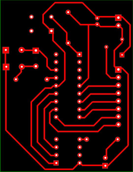
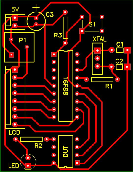
PCB


Subscribe
Login
0 Comments