Power-Saving PWM Solenoid Controller
- Rajkumar Sharma
- 544 Views
- easy
- Tested
- SKU: EL122096
- Quote Now
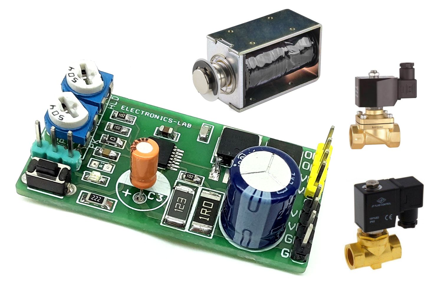
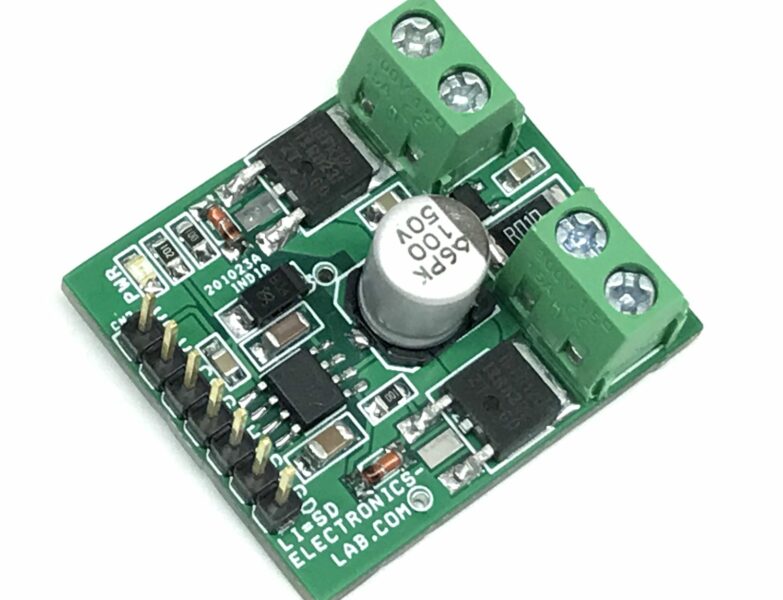
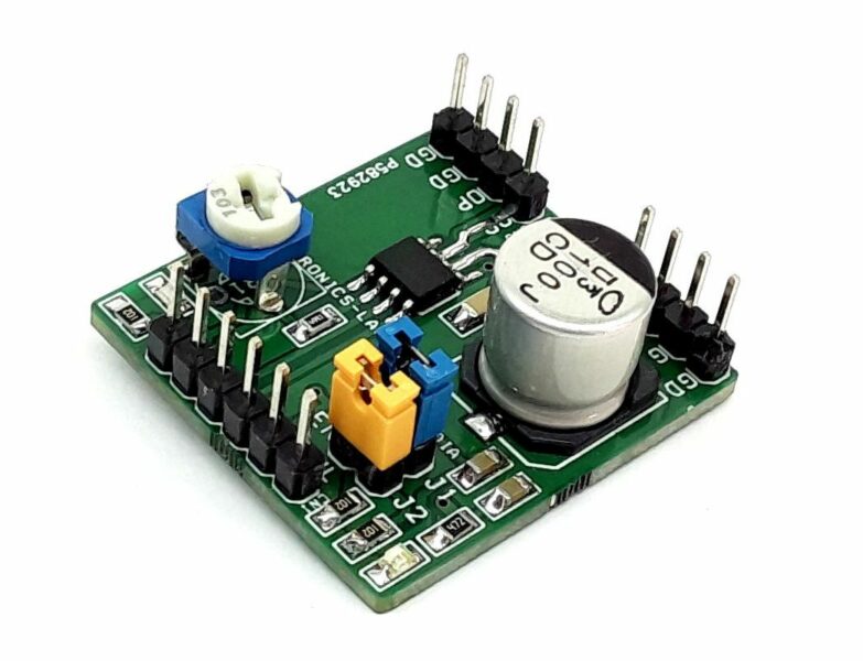
The project described here is a power-saving pulse-width modulator (PWM) controller for solenoids with an internal supply regulator. The board is based on the DRV110 IC which is a PWM current controller which is specifically designed for solenoid and relay applications. The project regulates the current with a well-controlled waveform to reduce power dissipation on the load. The solenoid current is ramped up fast to ensure the opening of the valve or relay. After initial ramping, the solenoid current is kept at a peak value to ensure correct operation, after which the current is reduced to a lower hold level to avoid thermal problems and reduce power dissipation.
Features
- Supply 24V DC (Range 15 to 48V DC -> Read Note)
- Load Current -> Read Below
- Fast Ramp-Up of Solenoid Current to Ensure Activation
- Protection, Thermal Shutdown, Undervoltage Lockout (UVLO)
- Solenoid Current is Reduced in Hold Mode for Lower Power and Thermal Dissipation
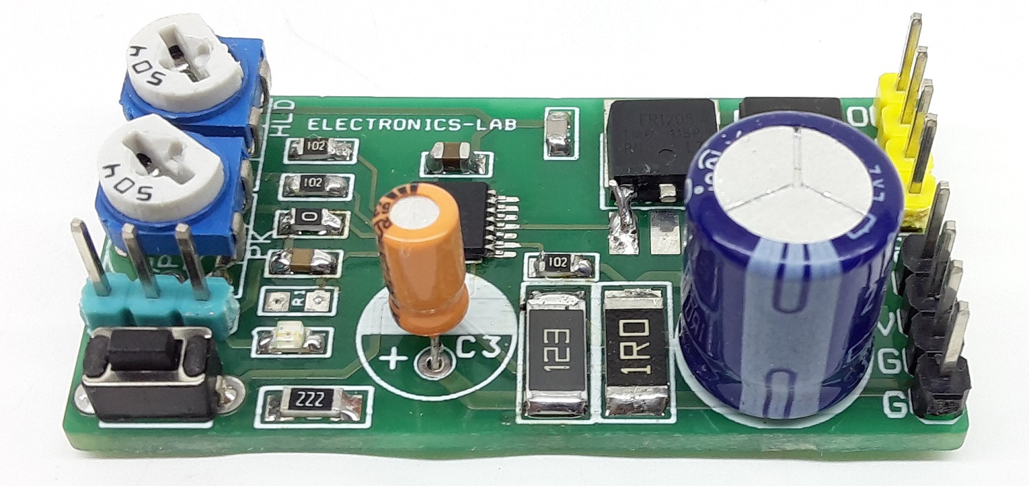
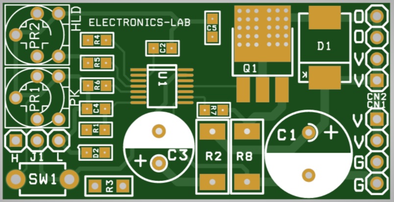
- IPeak (Peak Current) Adjustable Using Trimmer Pot PR1
- IHold (Holding Current) Adjustable Using Trimmer Pot PR2
- Jumper J1 Pull Low Disables the Output, pull high or Floating Enables the Output
- D2 Power LED
- Operating Frequency 20Khz (Can be altered), adjust resistor R6
- PCB Dimensions 46.06 x 23.36 mm
Components
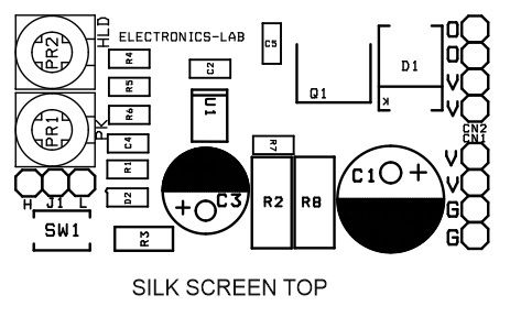
- D1 Power LED
- Q1 MOSFET to drive the Load
- D1 Clamp Diode
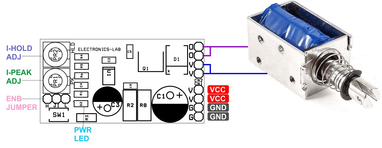
- CN1 power supply input
- CN2 solenoid Connections
- PR1 peak current adjust
- PR2 Hold Current Adjust
- Jumper J1 Enable or disable the Output
- Resistor R6 Frequency Adjust
Example Application Values when RSense R8 = 1Ohms
- Peak Current 150mA When R-Peak (PR1 + R4) = 400Kohms
- Holding Current 50mA When R-Hold (PR2 + R5) =200kOhms
- Keep Time 100mS When Capacitor C2 = 1uF
- PWM Frequency 20Khz
The peak current duration is set with an external capacitor C2. The peak and hold levels of the current ramp can be adjusted using trimmer potentiometer PR2 and PR1, as well as the PWM frequency, which can independently be set with external resistor R6. External setting resistors can also be omitted if the default values for the corresponding parameters are suitable for the application. The DRV110 device has an internal Zener diode that limits the supply at VIN to VZENER for applications that require a higher supply voltage. High DC voltages such as 48V can also be accommodated this way.
Enable Jumper J1
Enable and disable the switch is controlled by the EN pin. The EN pin contains an internal resistor network to set the pin to logic HIGH when the EN pin is floating. This feature can be used for situations where a control signal is not required and the solenoid is only energized when a supply voltage is present. Such applications could be valves or contactors. By pulling down Enable pin disable the output.
Configuring Peak and Hold Currents
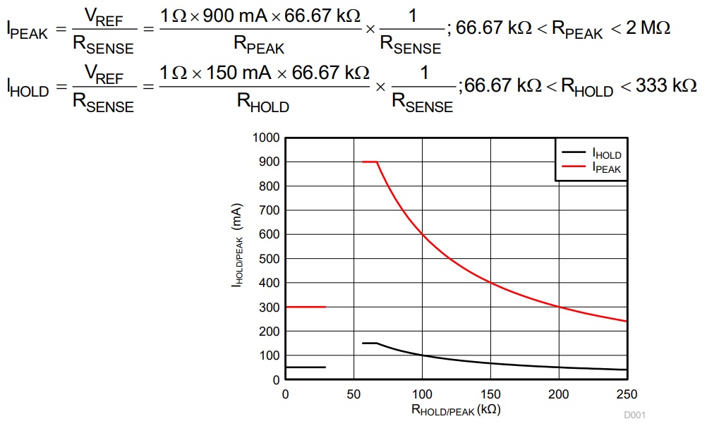
IPEAK and IHOLD depend on PR1 and PR2 trimmer pot resistance values RPEAK-PR1 and RHOLD-PR2 as shown in the circuit. If the PEAK pin or HOLD pin is connected to the ground or RPEAK or RHOLD is less than 43.33 kΩ (typical), then IPEAK is at its default value of 300 mA for IPEAK and 50 mA for IHOLD.
The IPEAK value can alternatively be set using trimmer pot PR1. For example, if a PR1 60-kΩ (= RPEAK) is connected between PEAK and GND, and RSENSE = 1 Ω, then the externally set IPEAK level will be 900 mA. If RPEAK -PR1 = 200 kΩ and RSENSE = 1 Ω, then the externally set IPEAK level will be 300 mA. It is not recommended to use a resistor between 30 kΩ and 55 kΩ to avoid the IPEAK or IHOLD current slipping from the maximum current setting to the default setting. In case RSENSE = 2 Ω instead of 1 Ω, then IPEAK = 450 mA (when RPEAK-PR1 = 55 kΩ) and IPEAK = 150 mA (when RPEAK-PR1 = 200 kΩ
Configuring the PWM Frequency Resistor R6 (Default Frequency 20Khz Resistor R6 Value 0 Ohms)
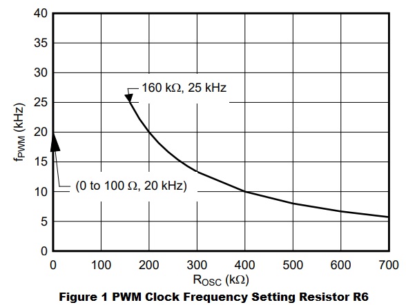
Frequency of the internal PWM clock signal, PWMCLK, that triggers each OUT pin ON-cycle can be adjusted by external resistor R6, ROSC, connected between OSC and GND. Frequency as a function of resistor value is shown in Figure 1. The default frequency is used when OSC is connected to GND directly. Use Equation 1 to calculate the PWM frequency as a function of the external fixed adjustment resistor value (greater than 160 kΩ).
fPWM=60Khz/R6-ROSC x 66.67kOhm; 160Kohm<R6-ROSC<2MOhms
OFF-STATE
OFF state In the OFF state, the EN pin is low and the PWM output is off.
PEAK STATE
The PEAK state begins when the EN pin is set high and ends when the tKEEP time has been reached. During this state, the PWM operates to reach the IPEAK current set by the RPEAK resistor.
Hold STATE
HOLD state In the HOLD state, the tKEEP time has been reached, and the PWM continues to operate but at the IHOLD level. This continues until the EN pin is set low again and the PWM turns off.
SHUTDOWN
The DRV110 turns off the gate driver in Undervoltage lockout (VIN < 4.6 V) or thermal shutdown (TJ > 160°C). If temperature shutdown is activated, the DRV110 resumes operation when the junction temperature is below 140°C.
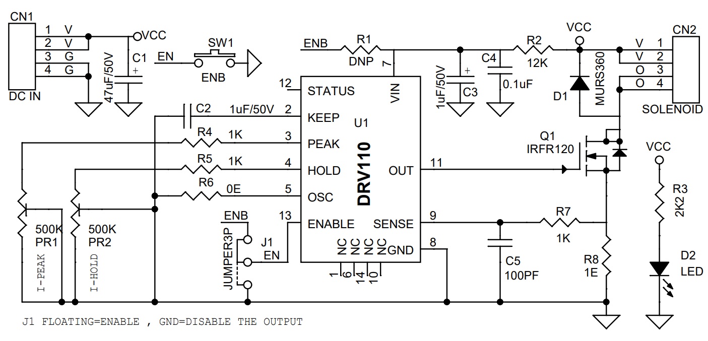
Schematic
Parts List
| NO. | QNTY. | REF. | DESC | MANUFACTURER | SUPPLIER | SUPPLIER PART NO |
|---|---|---|---|---|---|---|
| 1 | 1 | CN1 | 4 PIN MALE HEADER PITCH 2.54MM | WURTH | DIGIKEY | 732-5317-ND |
| 2 | 1 | CN2 | 4 PIN MALE HEADER PITCH 2.54MM | WURTH | DIGIKEY | 732-5317-ND |
| 3 | 1 | C1 | 47uF/50V | RUBYCON | DIGIKEY | 1189-3770-1-ND |
| 4 | 2 | C2,C3 | 1uF/50V | KEMET | DIGIKEY | 399-ESS105M050AB2EACT-ND |
| 5 | 1 | C4 | 0.1uF/50V SMD SIZE 0805 | MURATA/YAGEO | DIGIKEY | |
| 6 | 1 | C5 | 100PF/50V SMD SIZE 0805 | MURATA/YAGEO | DIGIKEY | |
| 7 | 1 | D1 | MURS360 | VISHAY | DIGIKEY | MURS360-E3/57TGITR-ND |
| 8 | 1 | D2 | LED SMD SIZE 0805 | LITE ON INC | DIGIKEY | 160-1427-1-ND |
| 9 | 1 | J1 | JUMPER3P WITH SHUNT | WURTH | DIGIKEY | 732-5316-ND |
| 10 | 2 | PR1,PR2 | 500K TRIMMER POT | BOURNS INC | DIGIKEY | 3362H-504LF-ND |
| 11 | 1 | Q1 | IRFR120 | VISHAY | MOUSER | 844-IRFR120TRLPBF |
| 12 | 1 | R1 | DNP | |||
| 13 | 1 | R2 | 12K 5% SMD SIZE 2512 | STACKPOLE | DIGIKEY | RMCF2512JT12K0CT-ND |
| 14 | 1 | R3 | 2K2 5% SMD SIZE 1206 | MURATA/YAGEO | DIGIKEY | |
| 15 | 3 | R4,R5,R7 | 1K 5% SMD SIZE 0805 | MURATA/YAGEO | DIGIKEY | |
| 16 | 1 | R6 | 0E SMD SIZE 0805 | MURATA/YAGEO | DIGIKEY | |
| 17 | 1 | R8 | 1E 1% SMD SIZE 2512 | PANASONIC | DIGIKEY | PT1.0YTR-ND |
| 18 | 1 | SW1 | TACTILE SWITCH | TE CONNECTIVITY | DIGIKEY | 450-1665-ND |
| 19 | 1 | U1 | DRV110 TSOP14 | TI | DIGIKEY | 296-30453-1-ND |
Connections
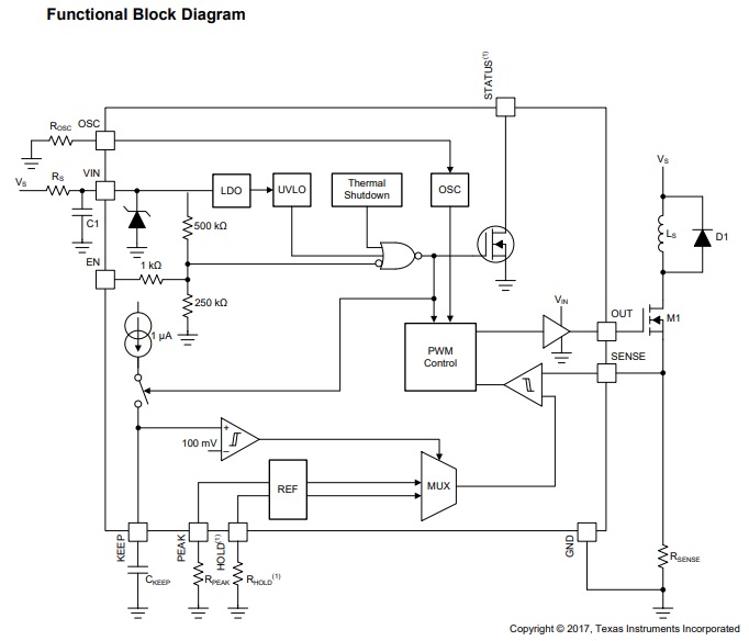
Block Diagram
PWM Frequency
IPeak and IHold Values
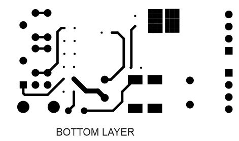
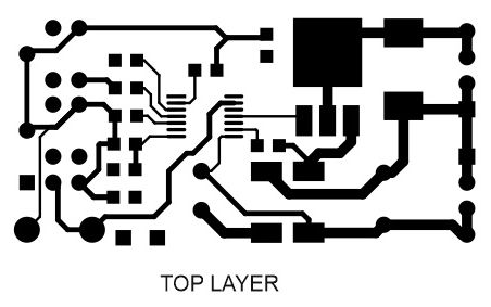
Gerber View
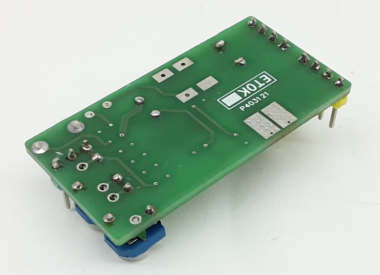
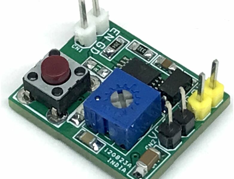
Photos