Stepper Motor Based Rotary Encoder with Clock and Up/Down Direction Signal Output
This project enables the users to use a stepper motor as a rotary encoder for position control and Up/Down direction control. A bipolar stepper motor can be used as a rotary sensor as it generates two channel strings of pulses by turning the shaft.

This project enables the users to use a stepper motor as a rotary encoder for position control and Up/Down direction control. A bipolar stepper motor can be used as a rotary sensor as it generates two channel strings of pulses by turning the shaft. The circuit provides Step pulse and Up/Down Direction signals by rotating the stepper motor shaft clockwise or counterclockwise directions. The outputs are TTL logic signals. The operating supply is 5V DC and the circuit consumes very low current.
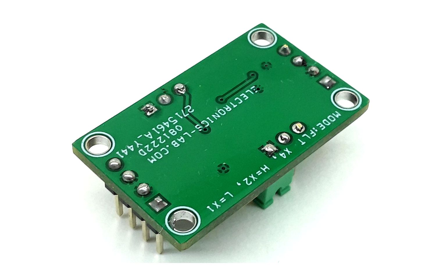
Mode Selection Jumper J1
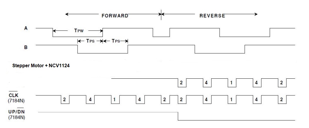
- Mode has a 3-states to select output resolutions X1, X2, and X4. The input quadrature clock rate is multiplied by factors of 1,2 and 4 in X1, X2, and X4 mode respectively, in the producing output.
RBIAS– Resistor R8 (Range 2K Ohm to 10M Ohms) – Refer to Figure below
- The value of this resistor is responsible for the output clock pulse width. Alter the value to change the output pulse width. Refer to the datasheet for more info.
Features
- Supply 5V DC
- Consumes Approx. 25mA Current
- Input to output delay 340nS for chip LS7184
- Input Protection 240V
- Easy Interface for Any Bipolar Stepper Motor
- Output Clock and Up/Down Direction
- Jumper for Output Pulse Multiply X1, X2, and X4
- PCB Dimensions 32.70 x 19.69mm
- 4 x 2.5mm Mounting Holes
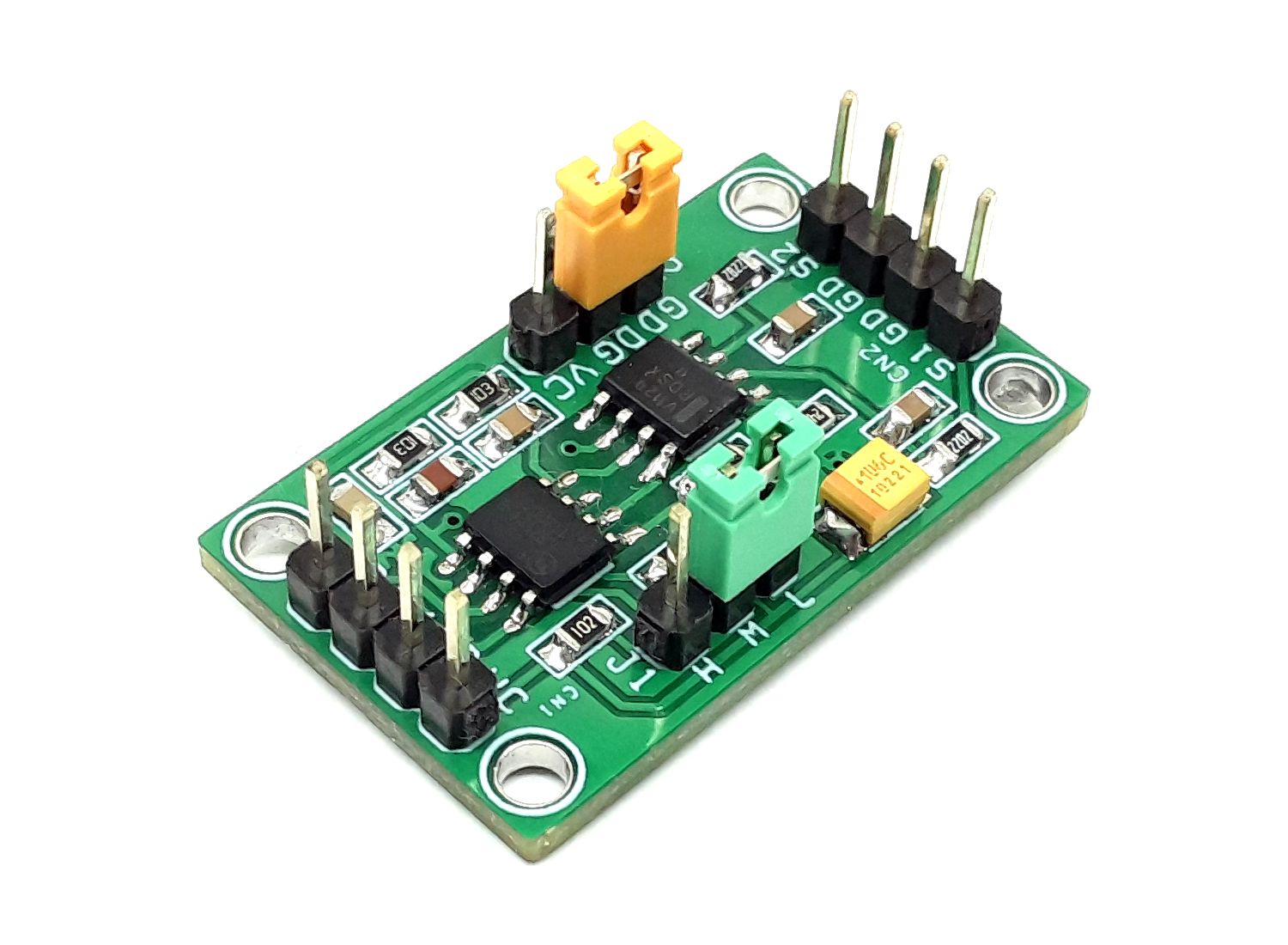
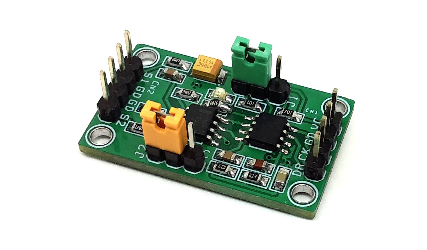
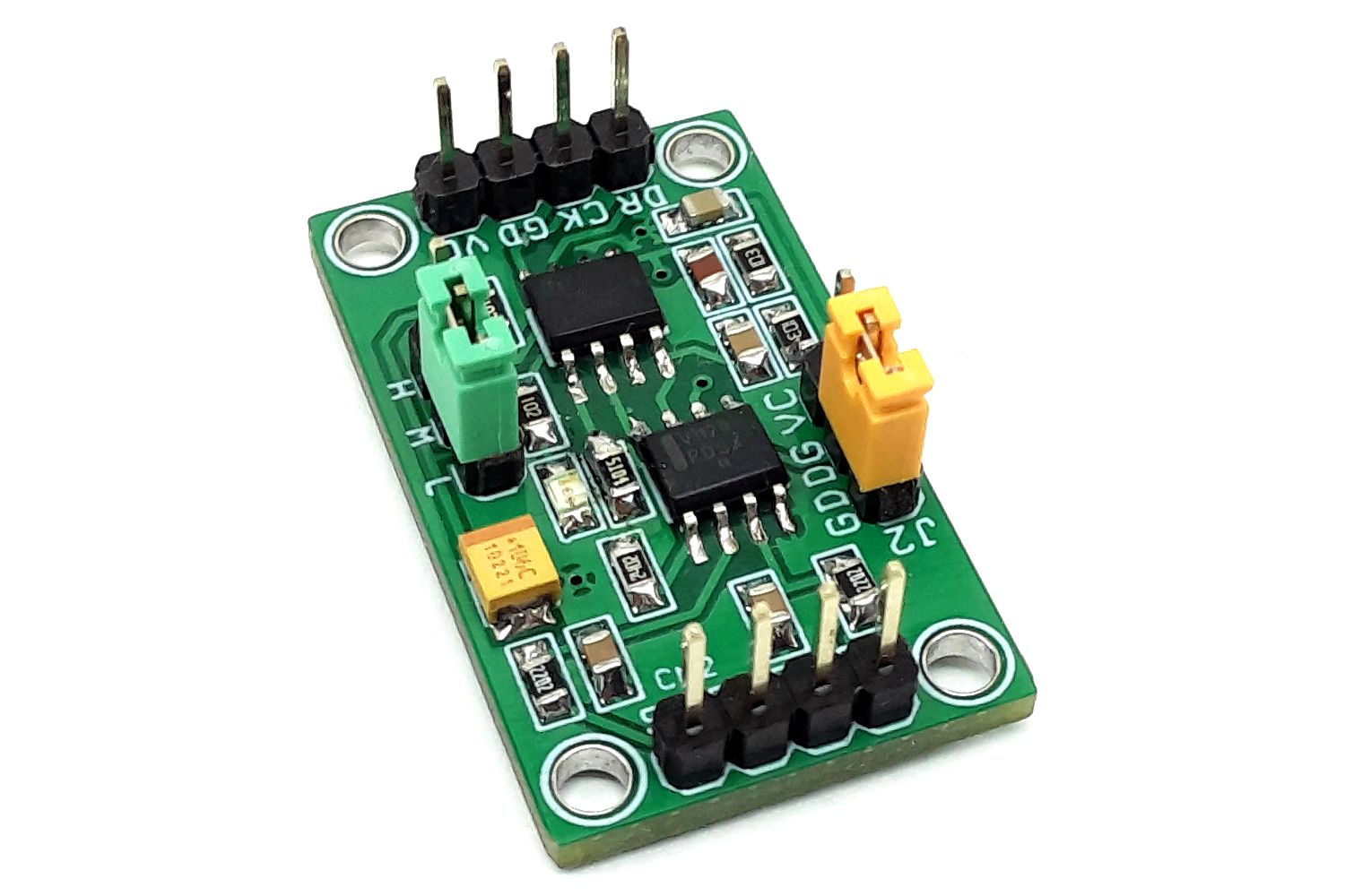
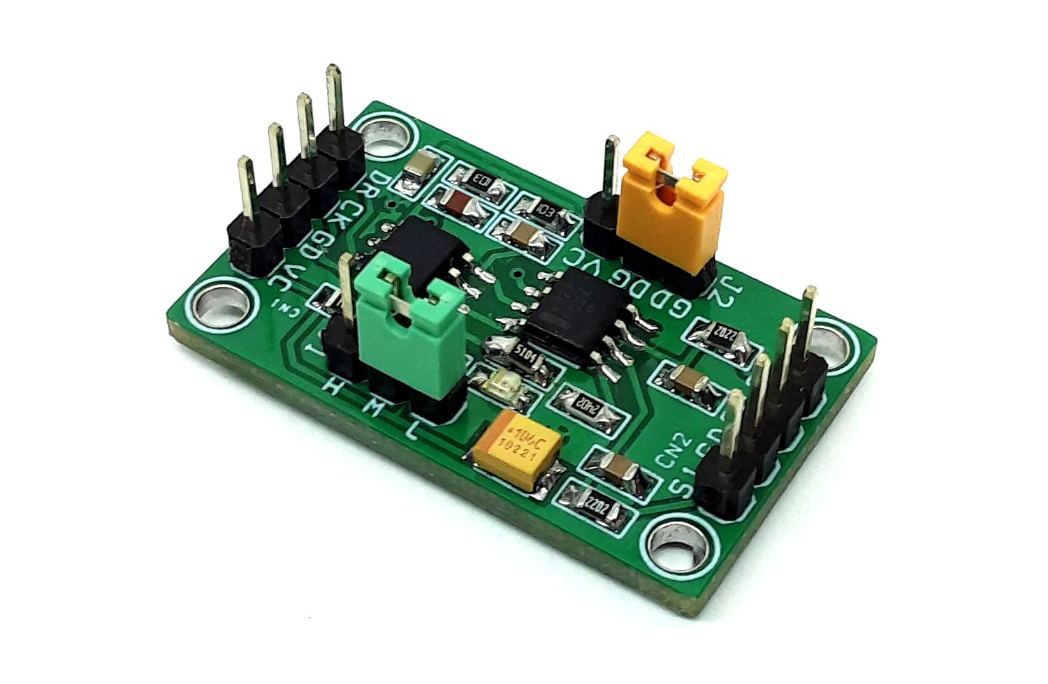
Connections and other details
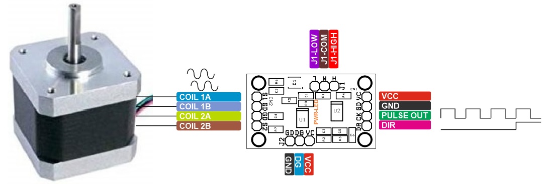
- CN1: Pin 1 = VCC 5V DC, Pin 2 = GND, Pin 3 = Clock Output, Pin 4 = Up/Down Direction Output
- CN2: Pin 1 = Input 1-S1 Stepper Motor 1A, Pin 2 = GND-Stepper Motor 1B, Pin 3 = GND-Stepper Motor 2B, Pin 4 = Input 2-S2 Stepper Motor 2A
- Jumper J1 Mode Selection: Jumper 1 VCC = X2 Output, Jumper J1 GND = Normal Output, Jumper J1 Open/Float X4 Output
- D1 LED: Power LED
- Jumper J2: Connect to GND
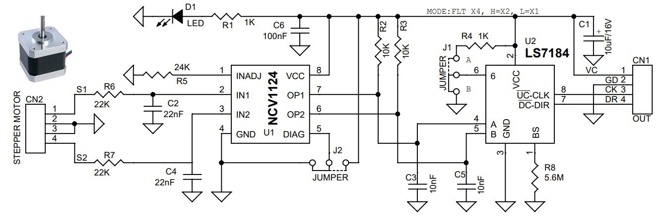
When the shaft of the stepper motor is turned two coils of the bipolar stepper motor generate two electrical signals which are connected to IN1 and IN2 of the U1 NCV1124 chip. The chip continuously compares the stepper motor output signal to a user−programmable internal reference. An alternating input signal of appropriate amplitude at IN1 or IN2 results in a rectangular waveform at the corresponding OUT terminal OP1 and OP2, both these signals are interfaced to the LS7184 quadrature clock converter. When both signals are applied to the A and B inputs of the LS7184 they are converted to Clock and Up/Down direction control. These outputs can be interfaced directly with standard Up/Down counters for direction and position sensing of the stepper motor. The number of pulses per rotation depends on the stepper motor output. Output pulses are proportional to stepper motor output. A standard 1.8-degree stepper motor provides 200 Pulses per rotation. Any small or big-size bipolar motor can be used as a rotary sensor.
Schematic
Parts List
| NO | QNTY | REF | DESC | MANUFACTURER | SUPPLIER | SUPPLIER PART NO |
|---|---|---|---|---|---|---|
| 1 | 1 | CN1 | 4 PIN MALE HEADER PITCH 2.54MM | WURTH | DIGIKEY | 732-5317-ND |
| 2 | 1 | CN2 | 4 PIN MALE HEADER PITCH 2.54MM | WURTH | DIGIKEY | 732-5317-ND |
| 3 | 1 | C1 | 10uF/16V TANLUM/CERAMIC SMD SIZE 1210 | YAGEO/MURATA | DIGIKEY | |
| 4 | 2 | C2,C4 | 22nF/50V CERAMIC SMD SIZE 0805 | YAGEO/MURATA | DIGIKEY | |
| 5 | 2 | C3,C5 | 10nF/50V CERAMIC SMD SIZE 0805 | YAGEO/MURATA | DIGIKEY | |
| 6 | 1 | C6 | 100nF/50V CERAMIC SMD SIZE 0805 | YAGEO/MURATA | DIGIKEY | |
| 7 | 1 | D1 | LED RED SMD SIZE 0805 | OSRAM | DIGIKEY | 475-1278-1-ND |
| 8 | 2 | J1,J2 | JUMPER 3 PIN MALE HEADER PITCH 2.54MM | WURTH | DIGIKEY | 732-5316-ND |
| 9 | 2 | R1,R4 | 1K 5% SMD SIZE 0805 | YAGEO/MURATA | DIGIKEY | |
| 10 | 2 | R2,R3 | 10K 5% SMD SIZE 0805 | YAGEO/MURATA | DIGIKEY | |
| 11 | 1 | R5 | 24K 5% SMD SIZE 0805 | YAGEO/MURATA | DIGIKEY | |
| 12 | 2 | R6,R7 | 22K 5% SMD SIZE 0805 | YAGEO/MURATA | DIGIKEY | |
| 13 | 1 | R8 | 5.6M 5% SMD SIZE 0805 | YAGEO/MURATA | DIGIKEY | |
| 14 | 1 | U1 | NCV1124 SOIC 8 | ON SEMI | DIGIKEY | NCV1124DR2GOSCT-ND |
| 15 | 1 | U2 | LS7184 SOIC 8 | LSI | GEMINI ELECRIC | |
| 16 | 2 | J1,J2-SHUNT | SHUNT FOR JUMPER J1 AND J2 | SULINS CONNECTOR | DIGIKEY | S9001-ND |
| U2 | LS7184 | DIGIKEY PART NO | 2808-LS7184N-ND |
Connections
Timing Diagrams
Resistor R8 Value vs Pulse Width

Gerber View
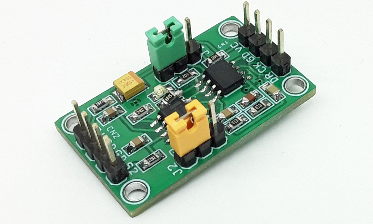
Photos
Video