

miniLOG – Precision Standalone Voltage Logger
- Jakub Felcenloben
- http://timecircuits.blogspot.gr
- jakubf2007@gmail.com
- 14.012 Views
- medium
- Non tested
- 0 Likes

miniLOG is a precise standalone voltage logger that save the data on a SD card. It has 4 basic analog channels:
- one has 12bit resolution for voltage measurements,
- two channels have 10bit resolution for voltage measurements and
- one channel has 10 bit resolution for current measurements.
Input voltage range is 0-25V and current range is 0-500mA. The data are written on a simple .txt file on SD card and can be further proccessed using spreadsheet software.
Description
This is my latest project called miniLOG. Its a basic data logger designed to have similar functionality to a data logging mode on some expensive $300+ multimeters for a fraction of the cost. It has four basic channels: a high resolution 12-bit voltage measurement channel with an MCP3201 ADC, two 10-bit voltage measurement and a 10-bit current measurement channel. Its capable of measuring voltage from 0 to 25V (with 0.0061V steps on the 12-bit channel and 0.025V steps on the 10-bit channels) and current from 0 to 500mA.
The miniLOG logs the readings onto an SD card which you can later plug into your computer, import the .txt file to a spreadsheet software like MS Excel and make graphs, charts etc.
AVR microcontroller
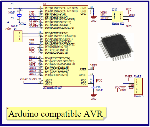
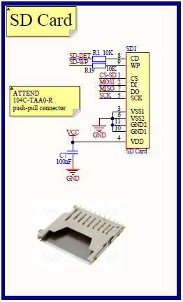
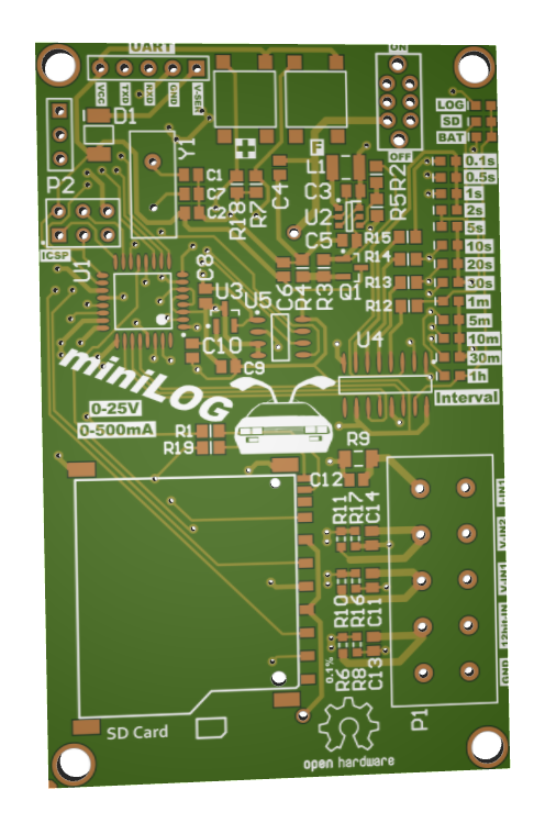
The miniLOG is based on ATmega328P-AU microcontroller in the TQFP32 package. It’s Arduino compatible so you can easily modify the code. It’s accompanied by a 16MHz crystal oscillator to reproduce the Arduino UNO circuit. You probably could get by without the crystal but since the entire Arduino bootloader operates based on that 16MHz crystal it’s a good idea to keep it. Also the miniLOG uses SPI interface to communicate with the ADC and the SD card so a little bit more clock accuracy is a good thing to have.
You can probably notice the 5 pin header. Its purpose is to connect to an external UART module like for instance a USB-UART or bluetooth-UART module. With a bit of extra code you can communicate with the miniLOG using USB or bluetooth. These modules are really cheap (~5 USD on eBay).
Analog to digital converter
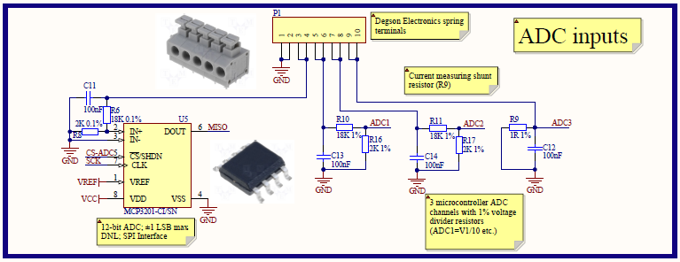
After a lot of research I decided to use the Microchip MCP3201 ADC. It’s a precise, low-power 12 bit ADC. The current measuring channel is basically the same as the others, it just uses a 1% 1ohm 500mW current shunt resistor. The miniLOG measures voltage across the 1ohm resistor. The safe maximum current is 500mA, although technically you could put up to 700mA through it. All voltage channels have voltage dividers dividing the input voltage by 10. Since the reference voltage in the circuit is 2.5V the maximum voltage onthese channels is 25V. The 12-bit channel requires something more precise, that’s why I used 0.1% resistors on that one.
Analog circuitry
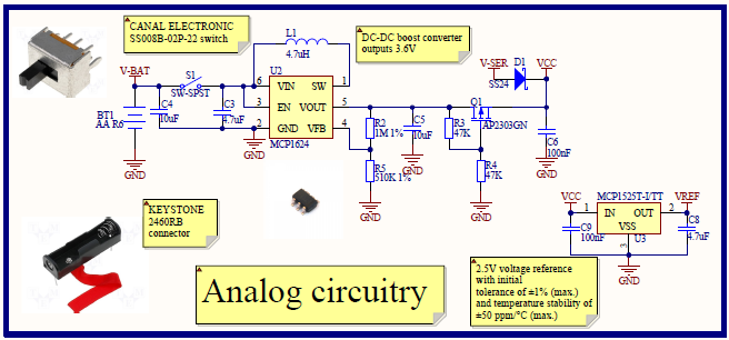
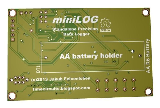
The miniLOG is powered by an AA battery. It’s connected with the main power switch to anMCP1624 DC-DC boost converter, which outputs 3.6V required by the rest of the circuit. The V-SER net is the voltage from the serial connector. If for example you want to power the miniLOG from a USB-UART module, two SS22 Schottky diodes and a P-channel MOSFET take care of it so the AA battery can’t burst into flames.
The voltage reference is an MCP1525, a 2.5V reference with 27 ppm/°C typical voltage drift. I decided to go for a convenient SOT-23 package for this one.
User interface
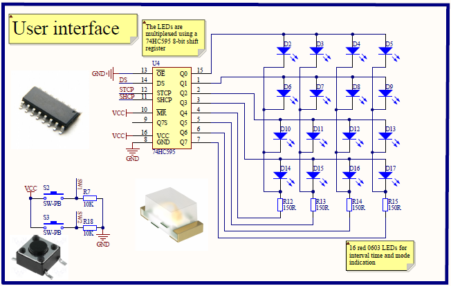
The user interface comes down to basic mode, channel and interval time selection. The user controls the miniLOG with two humble microswitches. The interval time and chosen mode is displayed using 16 0603 LEDs controlled by the 74HC595 8 bit shift register. It may seem silly to use 16 LEDs, but I have actually given it a lot of thought, took into account DIP switches, 7 segment displays, but this was by far the best solution.
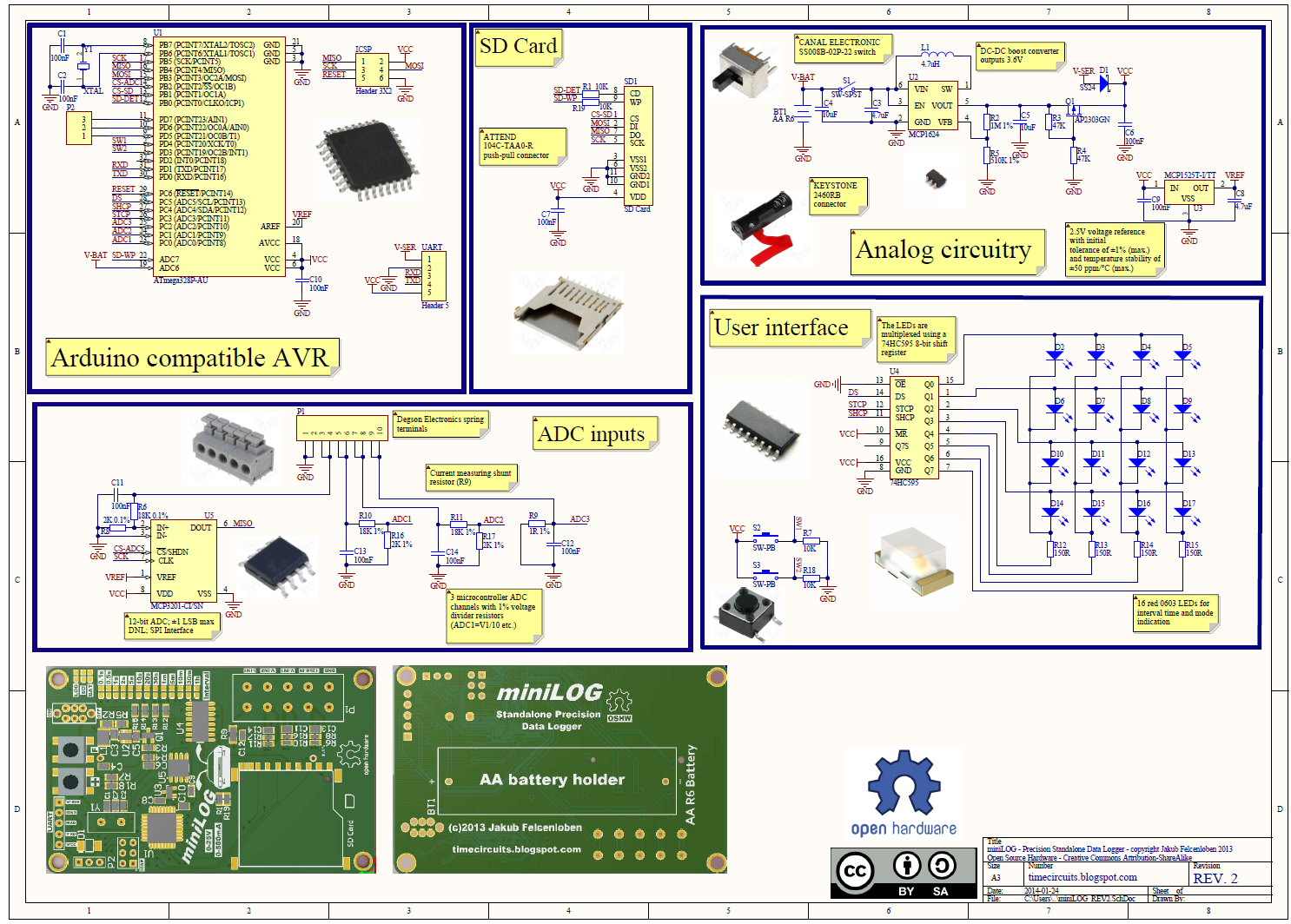
Schematic
The full schematic is show below
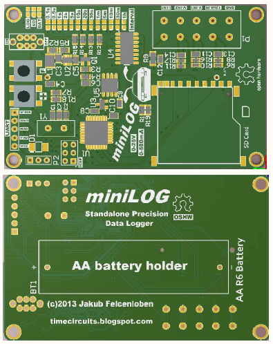
Photos
Buy miniLOG
The project is still at the prototype stage but should be available to buy in a couple of months.
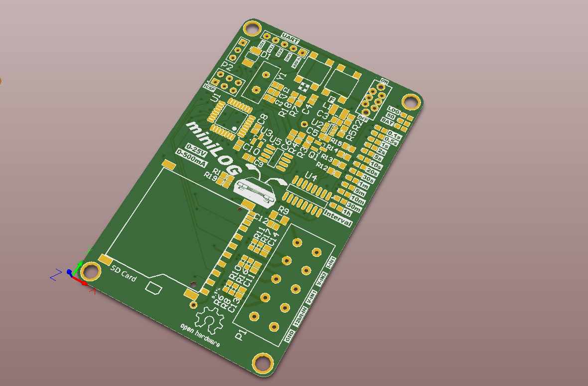
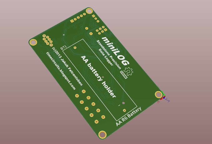
PCB


Please let me know when it possible to buy it. Best regards
Please contact the author above for details
I have an immediate use for 6 of them mesmerising the power on my standalone power system.