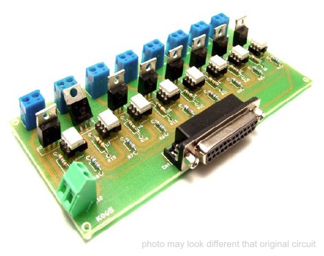
|
Opto-Isolated Stepper Motor
Controller
source:
wrb@cbnews.att.com
These are some very high-level instructions for building the
Opto-Isolated Stepper Motor Controller. Not really a lot to say. Most of the
construction is self-explanatory using the PCB artwork, the overlay, and the
schematic. Note that the pad for pin 1 on ICs and such are square
to help in proper placement. All ICs on the board are NOT oriented the same way,
so pay attention.

Download in ps
info - General info about the controller.
parts.txt - This is an ASCII file with the parts list
and some general info. This includes supplier info.
schmatic.ps - Schematic in Postscript format. This is
a tad rough because I used an HPGL to Postscript converter to make it since
Protel's Schplot doesn't do Postscript output.
overlay.ps - Overlay in Postscript format
pcb.ps - PCB artwork in Postscript form. This in a "normal"
view. That is, it isn't mirrored or flipped. This is the view you want to use
for iron-on methods.
test[123].exe - Test programs for parallel ports 1, 2, and
3. These programs step motor 1 back and forth.
step.[ch] - Source code for stepping motors. Really very
simple. It is written for Borland's Turbo C. Porting to another compiler
shouldn't be too much trouble.
If you're wire-wrapping, go by the schematic (you're on your own).
If you're using a PCB:
Using the overlay and schematic for direction, solder the parts in place on the
PCB. Resistors, diodes, and axial capacitors are mounted "stand-up" fashion.
MAKE SURE YOU CLIP U2's HEAT SINK ON BEFORE SOLDERING IT IN PLACE. It is
sometimes impossible to get on afterwards.

Note that you have two choices for the 5V supply. It can be
taken from motor supply via the provided 78L05. I have used this with no
problems at motor supply voltages from 8 to 16V. The UCN5804B draws a very small
amount of current. You can also provide your own 5V to the spare pad on the
control input side. Note that even though this is next to the ground input from
the PC, it is isolated from that ground (i.e. you can't take 5V from the PC).
Connecting the two grounds would compromise the isolation.
I've used two different methods for cabling. The cheapest and simplest is to
hack the Centronics connector off of a printer cable and use a continuity tester
to determine which wires go to which pins. If you're using the kit, the cable
used comes from MECI and has the following connections.
They are listed as color1-color2 where color1 is the wire color and color2 is
the stripe color:
WHT-BLU (2) (direction)
ORG-WHT (3) (step)
WHT-ORG (4) (half/full)
GRN-WHT (5) (motor 1 on)
WHT-GRN (6) (motor 2 on)
BRN-WHT (7) (motor 3 on)
WHT-BRN (8) (motor 4 on)
GRY-WHT (9) (spare)
GRN-BLK (25) (ground)
The ground conection to pin 25 usually works fine. On some PCs you may have to
connect pins 18 through 25 together.
The second method for cabling is to use a short pigtail connected to the board
with a DB-25 connector on the end. This allows you to use a straight-through
cable to connect the Controller to your PC parallel port.
Once you have it completed, connect a motor. The 6 outputs on the motor side are
as follows (viewed from component side with motor connectors to the left):
B
V+
D
C
V+
A
B-D go to one motor winding and A-C to the other. Refer to the schematic and any
docs on your motor for details. Apply power and check for 5VDC on the
output lead of the 78L05 (lead farthest from power connector).
Three simple test programs (test1.exe, ...) are included to help check the
operation of the controller. These are all the same except for the parallel port
they use for output. Test1.exe uses lpt1, etc. If you know which port
you're connected to (you may be surprised) then run the appropriate test
program. The motor should simply rotate back and forth in each direction. How
far it goes depends on the step angle of the motor.
If it doesn't work check component placement, cabling, etc. I'm assuming
some basic electronics building experience here (debug mode on ;).
If you are stuck, send me e-mail at wrb@cbnews.att.com and I will help as much
as I can. Good luck and have fun!
|