

FM Transmitter using MAX4467 & MAX2606
- Spiliopoulos Kwstas
- spilkos@windtools.gr
- 31.348 Views
- medium
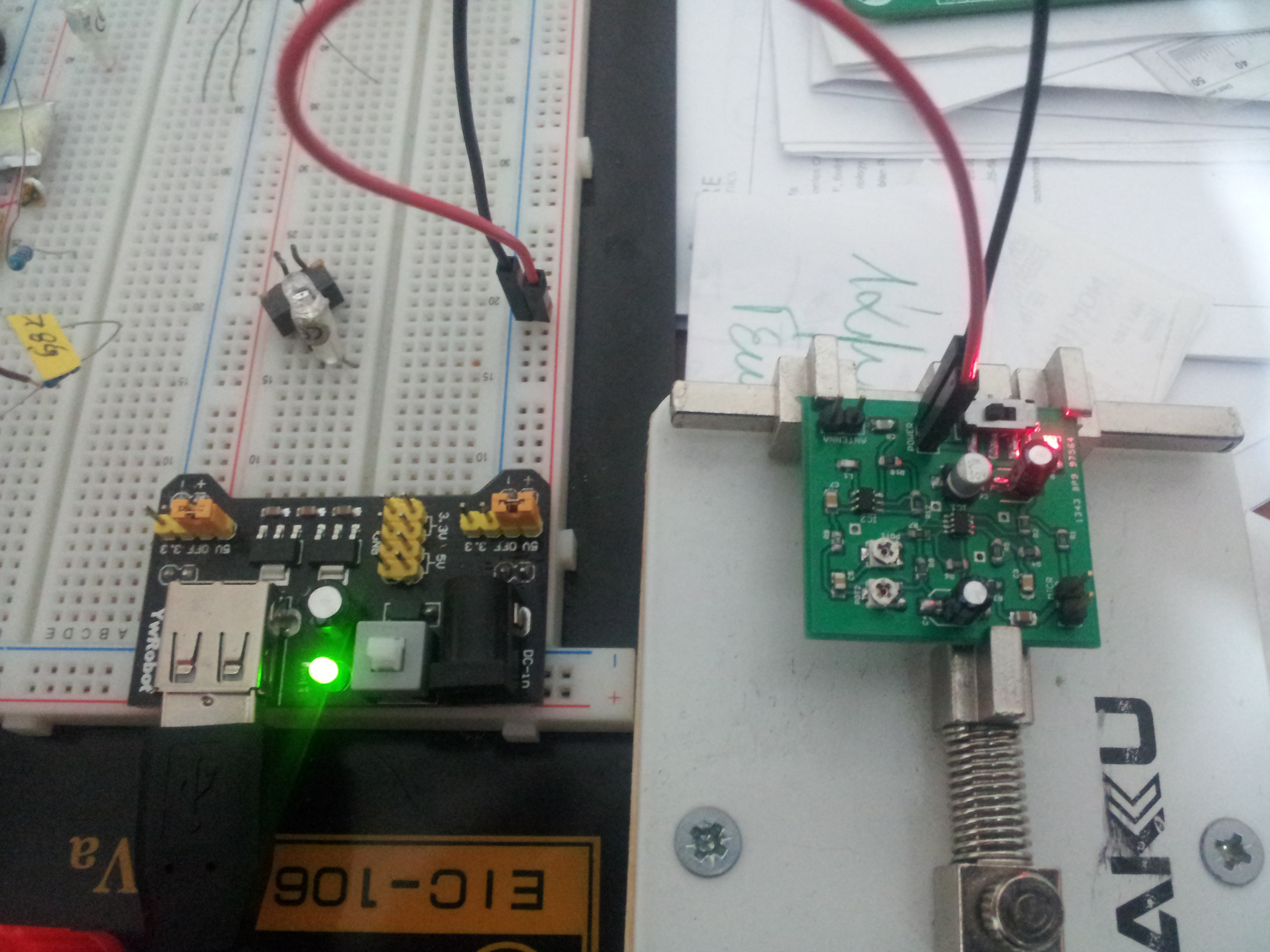
- Tested
- 0 Likes

his is a small circuit with two maxim’s ic, MAX4467 as microphone amplifier and MAX406 as VCO FM transmitter. It’s suitable for short range FM transmittion aka wireless FM microphone.
Description
This article originally published on in issue 323, July 2003 of Elektor magazine but a new PCB design is introduced here.
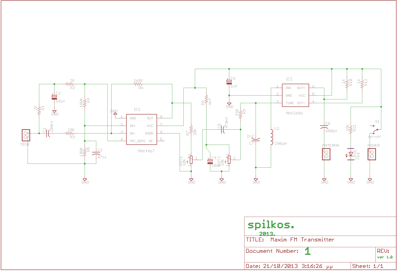
Here is a very simple, inexpensive and interesting project which provides lot of fun to a home experimenter or hobbyist. This simple transmitter can transmit speech over a short range. It can be used as a simple cordless microphone. The circuit uses two integrated circuits from Maxim. IC1 a MAX4467, is an amplifier raising the microphone signal to a level suitable for frequency modulation (FM). IC2 is a voltage-controlled oscillator (VCO) with integrated varactor (a.k.a. varicap diode). Its nominal frequency of oscillation is set by inductor L1. The inductor value 390 nH provides an oscillation frequency of about 100 MHz. For best performance, L1 should be a high-Q component. L1 may consist of 4 turns of silver-plated wire wound around a 10-mm drill bit, and stretched to a length of about 1.5 cm.
The wire diameter can be anything between 26 SWG (0.5 mm) and 20 SWG (1 mm). No core is used. The MAX4467 is a micro-power opamp for low voltage operation and providing 200-kHz gain bandwidth at a supply current of just 24 ΅A. When used with an electret microphone, some form of DC bias for the microphone capsule is necessary. The MAX4467 has the ability to turn off the bias to the microphone when the device is in shutdown mode. This can save several hundred micro-amps of supply current, which can be significant in low power applications particularly for battery powered applications like cordless microphones. The MIC-Bias pin provides a switched version of Vcc to the bias components.
Resistor R1 resistor limits the current to the microphone element. The output impedance of the MAX4467 is low and well suited to driving cables over distances up to 50 m. The MAX2606 intermediate-frequency (IF) voltage-controlled oscillators (VCO) has been designed specifically for portable wireless communication systems. The IC comes in a tiny 6-pin SOT23 package. The low-noise VCO features an on-chip varactor and feedback capacitors that eliminate the need for external tuning elements. Only an external inductor (here, L1) is required to set the oscillation frequency and produce a properly operating VCO. To minimize the effects of parasitic elements, which degrade circuit performance, place L1 and C5 close to their respective pins.
Specifically, place C5 directly across pins 2 (GND) and 3 (TUNE). Potentiometer P2 then lets you select a free channel by tuning over the FM band of 88 MHz to 108 MHz. Output power is about 21dBm (approx. 10΅W) into 50 Ω. P1 serves as a volume control by modulating the RF frequency. Signals above 60mV introduce distortion, so the pot attenuates from that level. To decrease stray capacitance, minimize trace lengths by placing external components close to IC1s pins. Using a wire antenna of about 75 cm the transmitter should have a range of about 35 m. Try to keep all leads as short as possible to prevent stray capacitance. The transmitter operates on a single supply voltage in the range 4.5 V to 5.5 V from any standard battery source. The transmitter must be housed in a metal case, with shielding installed between the two stages (AF and RF). Try to keep all leads as short as possible to prevent stray capacitance.
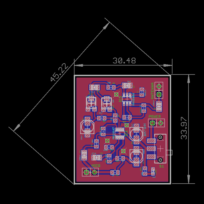
PCB
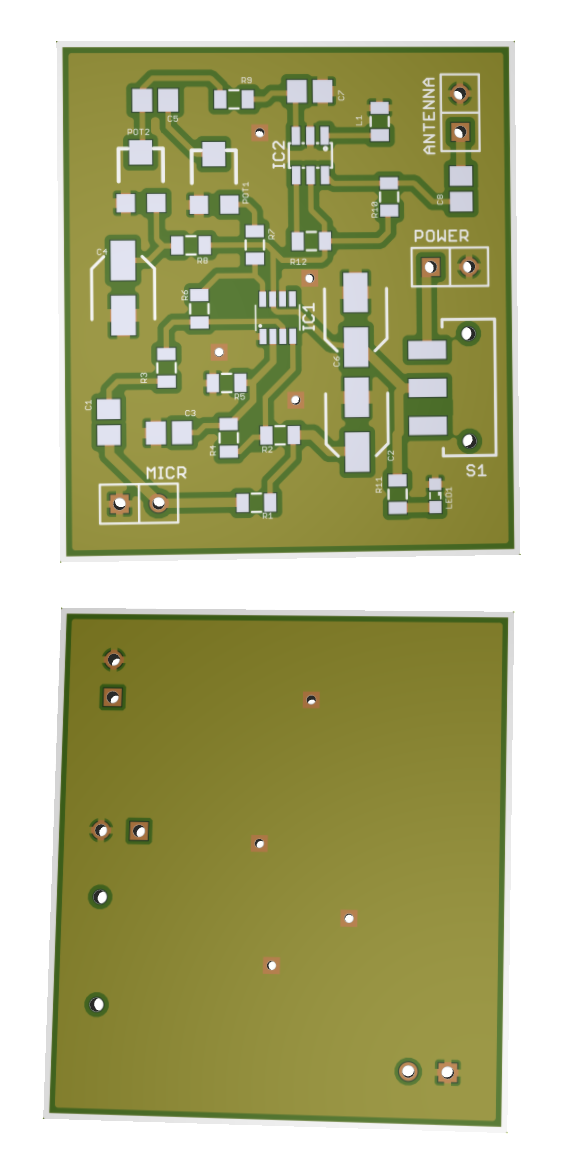
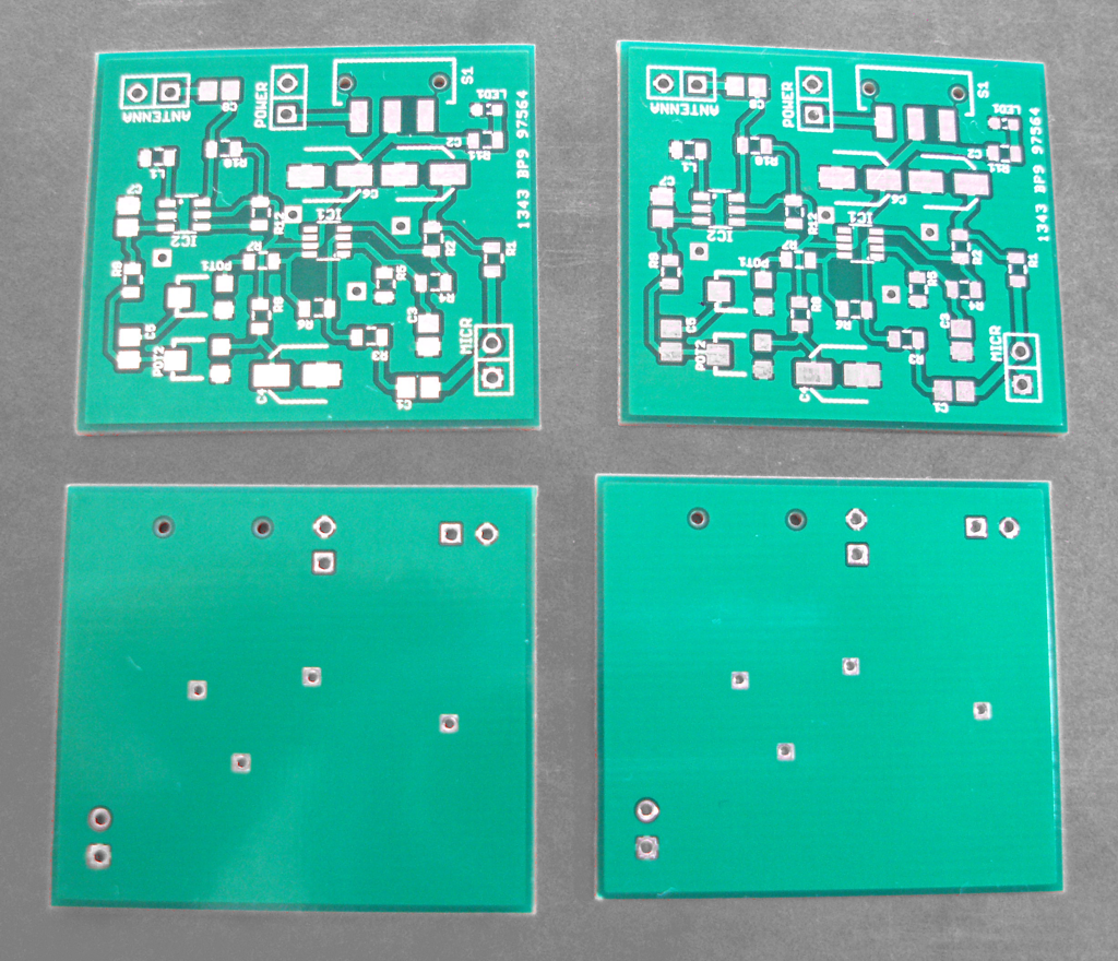
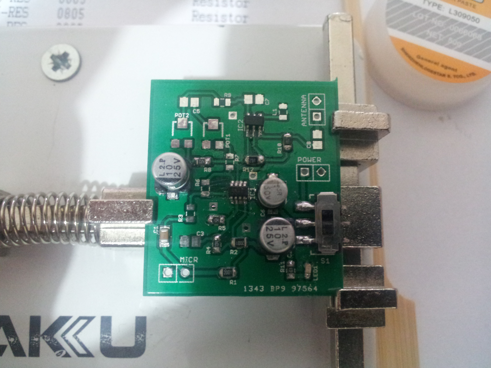
PCB


sir how t print a pcb layoout given by you
You can open and print the board with Cadsoft Eagle. Eagle will print it in correct dimensions.
Sir ,I don’t want to use power saving IC max4467 bcz power wastage not a problem for me and I want to o use this fm circuit in my mini project ,if it is possible please sent me pcb layout of this circuit without IC1(max4467).finally I want to know range of this circuit,thank you for your response
MAX4467 is a microphone pre-amplifier, so it’s required for this project to work properly. The range is FM band: 88 MHz to 108 MHz
how can this be interfaced with an lcd display
Hi.sir , I would like to make a powerful fm transmitter which can cover up to 50km to 80km but without using a dipole antenna. Please send me the circuit diagram and any relevant information.
For this purpose you will need a large power transmitter and antenna, so this is out o scope of this project. I don’t have something that can help.
Can I Chang the frq rang to go to the ham 2m band like 144mhz to 146mhz? Please email me back on this email a61bn@hotmail.com