

Plants Watering Watcher
- Audioguru
- 25.735 Views
- medium
- Non tested
- 0 Likes

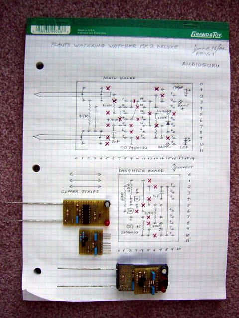
Using a Veroboard mother-board about the same size as the battery holder, a daughter-board was added to hold the remaining parts.
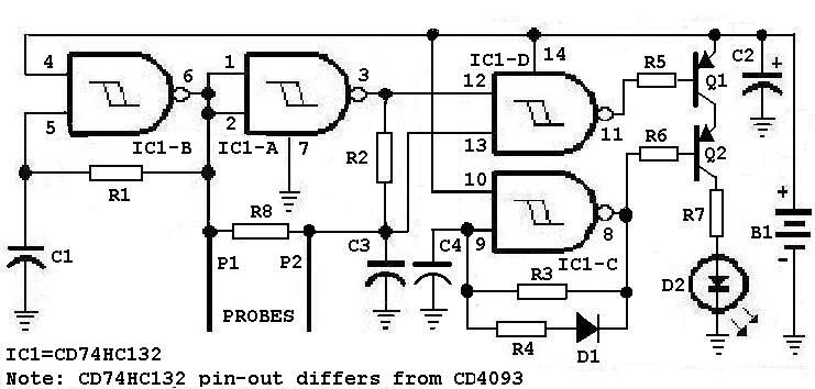
Schematic
Parts List
- IC1 . CD74HC132
- B1 … Two AAA alkaline cells, with holder
- C1, C3 1nF (0.001uF) or 2.2nF (0.0022uF)
- C2 … 100uF/16V electrolytic
- C4 … 220nF (0.22uF)
- R1 … 470K (all resistors 1/4W, 5%)
- R2, R4 100K
- R3 . 3.9M
- R5, R6 .. 680
- R7 . 15
- R8 . 47K
- D1 . 1N4148 or 1N914
- D2 . MV8191 or HLMP-D101A
- Q1, Q2 .. 2N4403 or 2N3906
Circuit Description
- IC1D is a CMOS Schmitt trigger oscillator at about 2KHz. It starts and continues to oscillate with a supply down to 1.24V (the lowest output voltage of my LM317 variable power supply) or less.
- IC1A is an inverter.
- IC1B is a Schmitt trigger NAND gate. Its output is low only when both inputs are at, or higher than the upper Schmitt trigger threshold voltage. With 47 ohms or less between the probes, an input is always low, so the output is always high. With a resistance of only R8 between the probes, the voltage across C3 is high most of the time, so the gates output is low for ½ the oscillators period. With a resistance that is halfway, then C3 is charged high by that resistance when the oscillators output is high, then is discharged when the oscillators output is low. When C3 is being discharged, then pin 12 of the gate is high, and pin 13 is also high until the discharging voltage of C3 reaches the lower Schmitt threshold voltage. During this time, the gate’s output is low. So the low time of the gates output depends on the value of the resistance between the probes. This is Pulse-Width-Modulation of the low output of the gate.
- IC1C is another CMOS Schmitt trigger oscillator at about 2Hz. D1 and R4 discharge C4 quickly so that its output is low for only about 15ms with a 3V battery, and about 25ms with a 2V battery.
- The series connection of Q1 and Q2 performs like a NOR gate, so that the LED lights only when both inputs to the transistors are low.
- R7 is a current-limiting resistor for the 1.8V LED. With a 3V battery, the LED current is about 35mA.
Circuit Operation
- When the soil is very dry, the LED flashes brightly, since the soils resistance is very high.
- When the soil has been watered a few days before, but is drying, the LED flashes dimly,
- When the soil is damp because it has been recently watered, the LED is off.
Note that different soils have a different resistance. Also, sometimes, watered soil will continue to have a high resistance until the soil absorbs the water, a delay of about one hour.
Although the LEDs current is 8mA with a 3V battery, it is lighted for only a maximum of only about 1/64th of the time, so its maximum average current is only 550uA. The remainder of the circuit draws 200uA. The total is 750A for new batteries, and about 250uA for run-down batteries. Therefore the exponential current of 300uA will continue with 1000mA/hr batteries for 2000 hours, or about 4.6 months.
The LEDs current is logarithmic with the soils resistance, so that when the resistance is one-half, then the LEDs current is one-tenth. If you water the plants when they need watering, then the average LED current will be very low, and the batteries should last for about one year.
Project Assembly
- Try to obtain the very bright and wide-angle LEDs that are listed. Samples are available from Fairchild.
- Use tinned copper 1.5mm diameter buss-bar wire about 8cm long for the probes.
- Use silicone caulking to attach and seal the Veroboard to the battery holder, and to seal the battery holders contact holes.
- Perhaps the project can be mounted in a plastic bottle for pills, available from a pharmacy (chemist?), with the probes sticking out of its lid.
Additional information: A list of plants and their watering requirements is here: Usermanual_moisture_meter_1820.pdf


")
Good ideas here am going to drive traffic by introducing my students here
Thanks! We really appreciate that!
its very good idea!]
FABULUS IDEA
I use this circuit to tap the variable PWM from pin 11 as input to a microcontroller to measure the duty cycle with direct register addressing. In 10 microseconds a reading and calculation is obtained from 5 periods with much higher accuracy then when using an analog low pass filter. Readings are made once an hour, extended sleep in between. Data transmission over 464MHz, and powered by solar cells. To be used for farming irrigation.