

JamesUWF
-
Posts
15 -
Joined
-
Last visited
Never
Content Type
Profiles
Forums
Events
Posts posted by JamesUWF
-
-
Pet Monster,
Have you taken a look inside your computer to see if there are any devices that regulate current to USB ports? Maybe something like a TPS2032D, or similar? If so, there is a chance it will have an OC output that is asserted when an overcurrent or thermal shut down occurs. You might monitor that output to give you some idea what is going on when you connect your battery to USB power. I'm wondering if (and how) the battery is discharging through that device when it is in shut down mode.
James -
Might be easier just to use a thermal lens with your mask, if you haven't already.
James -
You don't necessarily need a LCD controller. If you want to display video or VGA input, a COTS controller board would be an easy way to go. If you are just going using it as a GUI, then you can probably drive it with TTL signal levels. Does your controller board have any type of VGA or NTSC output? If so, this could make for a nice shortcut. After skimming through the datasheet, I'm guessing TTL appears to be the interface type, in which case designing a hardware interface shouldn't be too daunting. If I'm wrong and it's LVDS, then you will need a level translator IC. Either way, it's going to be quite a project, but a good one.
Sorry I've only skimmed the surface with this subject, as my time is limited, but I hope this gives you some direction to start with.
James -
I suppose you could, if you ran each of the 7447 outputs (a-g) through inverters, if you have some 7404's handy, before the resistors and LEDs.
-
If push comes to shove, that's what I'll do, but I was hoping to make it pull the same current regardless of any voltage change on the supply under test, using the feedback loop.
-
I did consider doing that with an inverting op-amp, but the control voltage I'm generating for the negative current regulator circuit is already taken from a -12V supply, thus already negative. Wouldn't this be the same as inverting a positive control voltage?
-
Sorry guys, those came out blurry. Here are the JPGs.


-
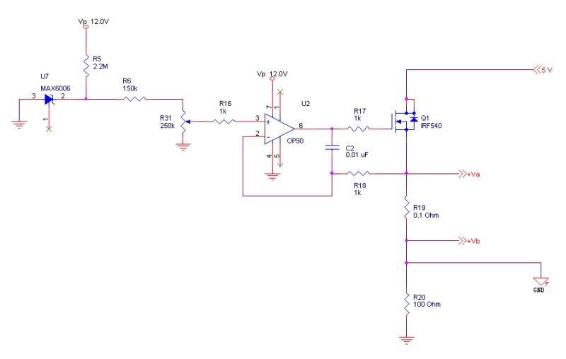
Hey guys, I'm working on a circuit that is an adaptation of something I found online awhile back. The first adaptation of the original circuit I made (shown below) draws a fixed amount of current from a positive voltage external supply. The idea is that the amount of current flowing through the N-channel enhancement MOSFET and the 0.1 ohm resistor is regulated through negative feedback and equals 10x the value of V+ on the op-amp. I have this version of the circuit working fine.
What I'm trying to do now is build a similar circuit that will do the same thing with a negative voltage external supply. The reference voltage being generated here is varied between -0.77 and 0 Vdc with the 250k potentiometer, and I'm using a P-channel enhancement MOSFET instead. The problem I'm having is that for some reason, this configuration is driving the op-amp Vout into saturation (-12 V), which of course is driving the D-S resistance of the MOSFET down to almost nothing. I'm not sure what I did wrong here, but I have a feeling I'm not setting up this op-amp properly for the new circuit.
Any thoughts? Suggestions?
[img width=680 height=408]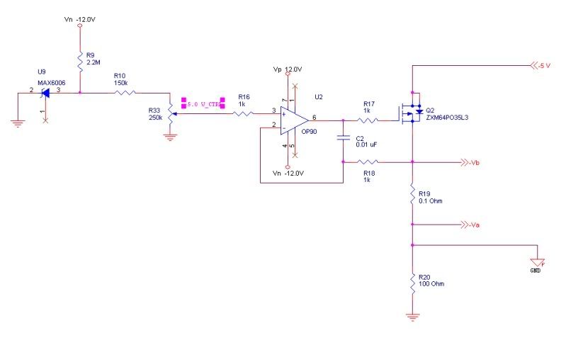
-
... the critical flaw with the "DCX rp" instruction is that it does not affect any carry flags, and odds are your delay string uses a "zero" dependent branch instruction to exit the loop.
Correction. I meant to say "...the "DCX rp" instruction does not affect any condition flags..." -
I'm not sure what kind of 8085A emulator you are using, but a real life 8085A will fetch and execute whatever instruction the Program Counter points to, be it "DCR M" or "DCX rp." Either of these instructions can be used to decrement a 16-bit number, but if you examine the instruction set closely, you will see there is a critical difference between the two.
"DCR M" decrements a 16-bit value located in two successive memory locations pointed to by HL and HL+1. "DCX rp" decrements the 16-bit value of a given register pair. While both decrement a 16-bit number, the critical flaw with the "DCX rp" instruction is that it does not affect any carry flags, and odds are your delay string uses a "zero" dependent branch instruction to exit the loop. So when you try to "DCR rp" your way out of the loop, your PC just keeps spinning around through it until there is a hardware interrupt, a hard RESET, or you kill the power.
I ran into the same problem the first time I coded 16-bit delay loops.
James


microprocessors
in Electronics chit chat
Posted
I learned everything I know about the 8085A from these two books:
Intel 8085A User's Manual (Intel Corporation 1985)
http://www.bugbookcomputermuseum.com/8085A-Cookbook.html
James