

chromei386
-
Posts
62 -
Joined
-
Last visited
Never
Content Type
Profiles
Forums
Events
Posts posted by chromei386
-
-
Feasibility study? They already make these
-
Looks cool
-
You will need to be specific in what you are looking for
What is the power (watts) requirements of the home appliances? Are they 110/240V AC appliances?
Will you be supplementing from the grid or is it a standalone system? -
I realise I was being a lazy bum.
Here's something more specific I drew up. I think it will work!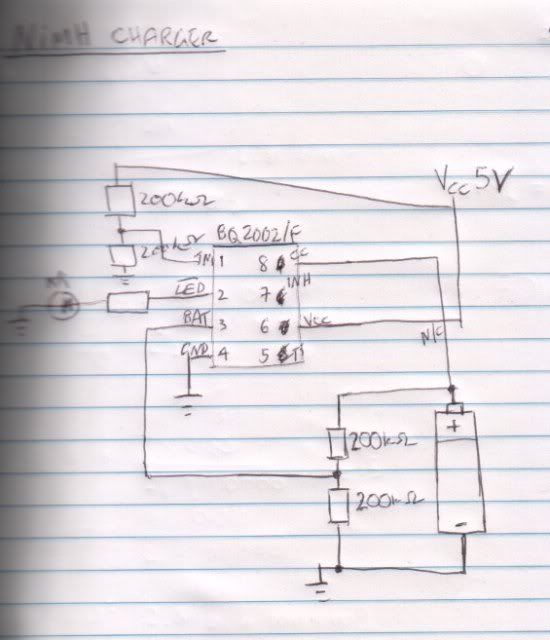
-
Maxim gave me the shaft, but Texas Instruments sent as International Priority Mail.
-
It may be easier to do it via a platform such as Arduino - http://www.arduino.cc/ - they have tutorials and sample code on hooking up sensors, adjusting sensitivity, sound makers, etc.
Designing projects is costly, and can quickly consume time and resources. Remember all this requires testing to make sure it works on the day.
Anyone who knows exactly how to do this properly won't be cheap unless you happen to have an engineer as a partner. Even then... !
Say you have everything technical sorted, what would the final product look like? You'd need an enclosure, with large buttons for selection, LED indicators for which sound is selected, pictures of each animal above? Where does the pressure sensor go? And all of this being "child proof" - which would be a huge consideration in design. Sensitive, calibrated electronics + Children = On the floor in pieces and wondering why you even bother getting up the morning
What is your budget in terms of time and money?
Even small projects have a way of taking up much more time and money than you would want or expect. -
Some key issues I see arising are:
How many LEDs and what type will it take to provide adequate lighting (if these are for replacements for normal street lights). What is the lighting requirement, is there any benchmark?
What is the power drain?
How will you store the energy - SLA batteries? NiMH? NiCd? How long will they be able to provide lighting at load requirements?
What are your weight requirements? (Large SLAs are heavy, and could pose a danger if up high).
What is your backup plan, if there is no sun for days. Do you feed from the grid? -
I'm not sure what you're referring to?
-
Don't attempt to solder the battery if it is not designed to be soldered as it may damage the battery / leak / explode (?)
Maybe buying a separate small battery holder instead would work? -
I think you'd be pushing your luck asking for them to pay for an air conditioner.
For buying one, check if someone is selling one via online classifieds - maybe one second hand- but quite new, i.e. they bought it 2 months ago and now are moving overseas, etc.
And make sure you get good warranty! You can sometimes negotiate extended warranties (on site) down to 20% of the asking price as these have a huge profit margin. -
What do you want the DC power supply to power? I'm not sure exactly of that model, but if you're doing using it to power sensitive electronics with ICs, etc, it would be better off with a stable regulated power supply. Maybe check if it's regulated..
-
I don't use Macs, but have you tried basic troubleshooting, such as trying different USB ports, checking cable connections, checking hardware devices. Maybe it just needs an updated driver from the Canon website. Or even just Apple system updates
-
Hi KevinIV,
That is not how I intended it to operate. I don't really know what I'm talking about, but this is my idea behind the design:
The 16V regulator comes from a computer PSU. The first voltage divider (20k/100k) acts as the Reference voltage - which is about 13.56V in real life - to the Voltage Comparator IC. The second voltage divider (15k/100k) acts as the Battery voltage reference, which is fed into the Voltage Comparator IC as well. When the Battery voltage goes higher than the Reference voltage, the Output from the Voltage comparator IC switches on an LED and switches off power to the battery via that relay - apart from a very weak trickle charge (via the 1k resistor which bridges across the relay).
The 3.3 Ohm resistor acts a voltage shunt and the voltage across it is the supply voltage minus the battery voltage. As the battery voltage increases, the voltage across the Battery voltage reference increases as well.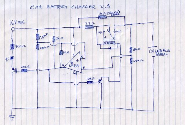
-
Oh I think I probably confused people with all the different diagrams. The battery is getting > 14V across the terminals when charging, as measured with multimeter as per the design, but the "supply voltage" comparison voltage for the voltage comparator is not getting above 12.8V. And in fact when I disconnect the battery, and measure open circuit voltage straight away it is still only around that 12.8V mark.
-
A follow-up, I have soldered this to perf board, and hooked it all up but there's a problem...
It charges at 700mA then gradually drops to say 500mA, but it never seems to get over 12.8V in the Vout at voltage divider at R8-R9. I can go up to 1100mA but I don't see it'll make a difference.... It's a 12Ah motorcycle battery, I have left it for a week charging I think at once, and still not really getting in 13V range.
And I topped up the fluid levels to just under MAX, but after a couple of days of charging some of them are almost below the LOWEST level! And it's not been overcharged, as the voltage was only 12.8V when I removed it. -
Hi,
I would like to make a reliable NiMH battery charger - using the BQ2002FPN IC Controller Fastcharge (8-DIP) - datasheet here: http://www.chipcatalog.com/TI/BQ2002FPN.htm
I was originally going to use a Maxim product but they decided they didn't find me important enough to send it to, whereas Texas Instruments sent me an alternative to me via International Priority Mail, arriving two days later from Malaysia.
Anyway, I digress.
I have this IC on my desk, but I don't know how to go about designing or using this as a charger. Do I just connect the outputs to the battery and give the IC power and that's it, it's done? Or is it more complicated? I have read the datasheet 3 times but unable to really process the information.
And as a bigger picture question, is this a good way to go about building a battery charger? And I can just build four stand alone circuits and have a nice battery charger bay? And is the temperature function a really important feature or is relying on delta V good enough? -
Which bench power supply do you use?
What are its features / likes / dislikes?
Please post a link if it's a project you built from schematics online
I use a Dell computer power supply with +5v and +12v rails. It does the job, but I am looking for something more robust and adjustable with voltage range and current limiting. -
Just in case anyone was following this, here's a pic of the prototype:
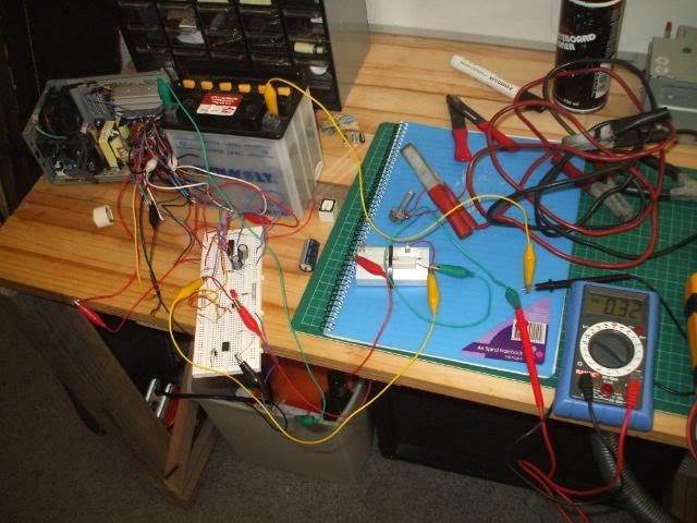
It appears to functioning correctly. I have limited the current more than normal as I am using thin aligator cables.
Oh and the power is coming from the 5V and -12V rail, which is giving about 16V. I tried tapping into the regulator and changing one of the resistors, but that didn't work and it's really crammed and I can't see or move anything! But this works for this purpose. -
Hi, I am about to start a project of converting a 400W ATX power supply from computer into a bench supply. +12V, -12V, +5V, -5V, +3.3V, -3.3V connections
I've done it before with a 150W PSU and I use it all the time.
Do you think electronics-lab may want to add this article/project (with pictures and tutorial) to their projects section?
Or is a bit overdone already? -
I've fixed up so they are common emitter, thanks for the tip:
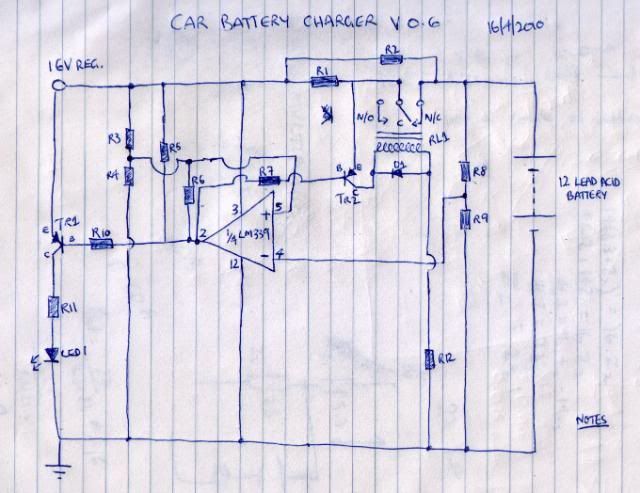
How would I find out the forward voltage drop over the lead acid battery while charging? I suppose that may not apply it's not an active device. Would it just a matter of measuring the battery's internal resistance and using Ohm's law? (edit: it is the charging voltage of the battery, the excess voltage will drop over the resistor)
It appears I may be charging this battery at about 16V (edit: no, I'm not -> the excess voltage drops across the resistor in series)
Maybe I'd be better off using 14V and supplying the IC chip 16V from another power out in the PSU (common ground). (edit, no it's fine)
I may have designed this whole thing badly :) (edit: maybe, but it appears to work) -
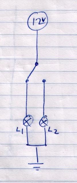
From what voltage source? Batteries? Power supply unit? Wall wart?
To get the right mA to your LEDs, use this formula:
R = (Vs - Vl) / I
where R = resistance
Vs = power supply voltage
Vl = sum of LED voltages (check, but probably 2v ea)
I = LED mA = 30mA
you could hook them all up from a 12V DC source - having 5 LEDs per 'leg' and have 10 'legs' in parallel.... with some quick calculations that's
R = (12 - (5x2)) / 0.030
= 67
so you have 5 LEDs hooked up in series with a 67 ohm resistor....... then hook up 10 in parallel with power supply.
the circuit draws 30mA x 10 = 300mA
so you just need a 12V DC power supply capable of delivering 300mA (easy to buy, find or make!) -
My interpretation of that question would be:
-
I picked up a 400W 12v to 240v inverter from Kmart (Aust.) for $30 AUD. It has a fan and a bunch of MOSFETs along with the usual transformers & capacitors. It works well and if it breaks down I refund it. I couldn't buy the parts separately and build one myself for that price. It's clean enough to run a PC from...
-
As promised! I'm really pretty good about it but I'm sure I've missed something
Car battery circuit design - comments, feedback?
in Electronic Projects Design/Ideas
Posted
Thanks, I do think constant source of current to the battery would be very useful to charge the battery faster