

autir
-
Posts
196 -
Joined
-
Last visited
Never
Content Type
Profiles
Forums
Events
Posts posted by autir
-
-
In a "typical" (if such a thing exists) Line-in interface
-> What is the input impedance ?
-> What is the Vp-p(max) ?
-> Do PC Soundcards' specifications differ?
Thank you. -
Quoting from http://www.epanorama.net/circuits/microphone_powering.html:
Basic electret microphone powering circuits
Basic circuit
+---------------------------- battery +ve (3 to 12 Volts)
|
2k2 R1
|
o---------- 10uF ------o----- output
|+ |
CAPSULE 10k R2
|- |
+----------------------o----- GND, and battery -ve
This is the basic electret microphone powering circuit which you can use as generic reference when receivign circuits which use electret microphones. The putput impedance is determined by R1 and R2. If you leave out R2 the output impedance is roughly the resistance of R2.
-> How exactly is Zout calculated?
-> What is the internal Z of a typical electret capsule?
-> What is a typical Vp-p value produced from such a circuit?
Thank you.
-
I know there are some Greeks among the members of this forum.
Can anyone please tell me where I can find a Strip Board Cutter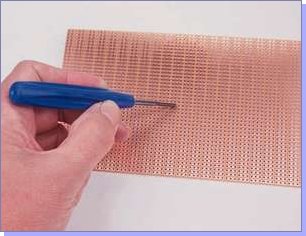
or something similar in Athens?
Thank you. -
Hi ducestaley85
I doubt that there are educational videos for electronics. And even if they exist, they will be much inferior to a good book. If you want to begin studying electronics, you should go to a bookshop and buy a book of basic electronics: theory and simple circuits with diodes, capacitors, transistors etc. Depending on your region, you can also try a library. Beware of the needed mathematics level required to comprehend the book. Also beware of its age: A 1960 book dedicating most of itself on tubes would be not a good beginner's book. I am sorry I am unable to make recommendations but my few electronics books are not written in English ;)
Regarding software, you should definitely get a simulation program. This will save you time, burnt components and much money spent on equipment (at least for the start). The only one I have tried is the Electronics Workbench Multisim series. Currently using Multisim 7 and for the simple circuits I build I am very satisfied.
Cheers -
Hello
Does anyone know of any programs which take a circuit and transfer it to stripboard?
The only two programs I know exist are Stripboard Designer and Stripboard Magic. The first one I have not tried, but people say it is way inferior to Stripboard Magic, which is impossible to locate.
Any suggestions?
(p.s.: If there could be any means of interaction with Multisim 7, I would be pleased. I know I ask too much ;D) -
Hi ducestaley85
Very few (if any) people post breadboard drawings along with their scematics. The main reason is that by carefully reading a scematic it is easy (for a simple scematic, at least -
Exactly what I needed! Thanks.
Can you explain in plain English ;D what is the difference between "Maximum amps for chassis wiring" and "Maximum amps for power transmission"? -
My amp hums even with no input.
The case and audio ground of a computer might be connected to the ground wire of the mains but your amp shouldn't be.
Why? What happens then?
Both in the old circuit and in ST's datasheet all grounds are connected: input signal ground, output signal ground, power supply ground. So is the case in my circuit.
The power supply I used for the test was an LM7805-based circuit.
My output cables are shielded audio ones. My input cables are wires from UTP cable.
I have not soldered any connectors yet. Used cables with crocodile clips to connect to power, input, and output.
-
I have good news and bad news.
The good news is that it works. I was very surprised to listen to the music coming from the speakers. It is the first circuit I have ever built - breadboard prototypes don't count - and soldering on the stripboard was a new painful experience. I was pretty sure that I must had done something wrong, you know...
The bad news is that from the speakers there comes a constant humming which does not depend on the volume of the input sound. The circuit is grounded both to the signal ground and to the power ground. If I disconnect the circuit's ground from the signal's, the humming decreases. If I touch the earth cable with my fingers, the humming stops.
edit: Almost forgot. There exist some high frequency oscillations, too. frequency is constantly increasing. When I touch the ground everything stops.
Anything to suggest? -
You mean this lovely product, Philips Contact Cleaner, they sell in electronics shops? Now it has 1001 uses ;D
One last question: Could you please check the polarity of capacitors C7 and C8? There is something suspicious... -
I have modified the circuit according to your corrections. Now the only difference from ST's circuit are capacitors C7 and C8 which are 1 instead of 0.22 uF.
In reality R1 and R2 (the only resistors in the new circuit) are a 6-pin linear potentiometer, chassis-mounted.
-> Does its value - 10kOhm - play a role?
-> Is there a special oil I can use to lubricate it so as to minimise noise when adjusting it?
-
Something less expensive?
Do you have it in copper? ;D -
!
Won't this charging current blow the transformer's two fuses? Even if they are slowblow? -
A little snippy there? Sometimes people are doing other things. Be patient.
Relax. I didn't bite -
Once more you are right
-
Ok. Let me rephrase the question.
I want a cable (single-clone copper wire would be better) which can support 1A (DC or RMS) and which can fit inside a veroboard-type hole. -
It doesn't matter since your power supply probably has at least 1000uF in parallel.
The PSU powering this circuit was a linear transistor - two diodes - capacitor...
Ok, C12 will be changed to 100uF.
Because your circuit has R5 and R6 in series with them so their value can be lower.
Shouldn't I replace them with two 100uF caps and omit the resistors? Fewer components are always welcome -
No. Polarity is extremely important with polarized capacitors, that is why it is marked. If they are installed backwards they blowup like a bomb if the charging current is high enough! Carefully try it.
With a low charging current a backwards polarized capacitor leaks a lot of DC current and its capacitance decreases over time.
I know all this. What I asked is ...hmmmm... take for example the circuit of the preamp. Why do input C3 and output C4 have the polarity they do?
When we design the next stage of this circuit, is the input capacitor of this stage supposed to have its "-" facing C4's "-", so as to form a non-polarised cap? Wouldn't the proper thing be to replace C4 with a non-polarised series of two electrolytic caps, so as not to pay attention to the polarity of the input cap at the next stage?
Another question: If we don't need a polarised capacitor to block DC, why do we use elctrolytics? Why not just use an inexpensive 100nF ceramic, for example?
-
Yes, now I see that I transferred the Vcc part of the circuit to Electronics Workbench with this error
-
audioguru,
What would be the ideal transformer for this circuit? If I'm not mistaken, it should be rated as 0.5*squareroot(2)=0.7 A and [12+3(for the Vi-Vo)+2(for the bridges)]*squareroot(2)/2=12 Volt. What have I calculated incorrectly? -
The speakers of my PC started to act strangely, and I thought that the time had come to redo some solderings. I opened the speaker containing the amplifier and saw the circuit. It is based on the TEA2025 from ST. I desoldered all components and I'm about to rebuild the circuit on a new board.
The circuit was nothing like the circuit proposed in the TEA2025's datasheet.
I attach it here in case anyone can explain why have they altered all these things.
note: Input connects to R3 and R4, output goes to C3 and C4. R7 and R8 are optional and used when connecting headphones.
Edit: I corrected the error with C12, R3 and R4 in my circuit. Several times ::).
-
Then the electrolytics at the output, they reduce the dynamic output resistance(impedance).
Why/how?
Also: Can anyone spare some time to explain how we calculate the values of the proper transformer for this (and a similar) circuit?
-
By the name "veroboard" I was referring to the type of the board, not a specific brand. What is the difference, if any, between a veroboard and a stripboard?
-
A fine answer indeed! ;D
What I've understood is that:
-> We do not need polarised capacitors. We use electrolytic capacitors not because of the polarity they posess but because of their high capacitance values. Electrolytics in this case can be installed in either direction, their polarity is unimportant. The proper thing to do, regarding quality, is to use expensive film capacitors of the desired values.
-> The only case we really need a polarised capacitor is when blocking DC or connecting stages whose voltages differ by far.
Questions:
Why do electrolytic capacitors produce higher distortion than film ones? Is it a symptom of the polarisation of the electrolytic capacitor, or does it depend on the different nature of the two species?
Why do two polarised capacitors connected in series produce a non polarised capacitor? Does it matter whether the + or - ends are the ones connected?
To construct a non polarised capacitor by connecting two electrolytics is exactly the same with bying a non polarised electrolytic?
Can't we block DC or voltage differences in general with a non polarised capacitor? Is polarisation really needed?
What do you mean by that?The author was too careful by using the non-polarized series connection of C1 and C3 because the electret mic draws only about 500uA and the voltage at its connection to the cap will be a high voltage, while the cap's connection to the transistor's base will be only 0.6V.
What do you mean by that?putting both polarities across a coupling capacitor
Thank you :D


Stripboard CAD
in Spice Simulation - PCB design
Posted
I found it. I am downloading it as I write.
http://www.electronics-lab.com/forum/index.php?topic=3757.msg23676#msg23676
Thanks!