

wiparat
-
Posts
9 -
Joined
-
Last visited
Never
Content Type
Profiles
Forums
Events
Posts posted by wiparat
-
-

This circuit is IC implementation schedule. No. 555 applied with IC number LM3905.By the IC to the number 555 are the circuits Stable multi-vibrator. How often do produce it.This frequency is then forwarded to the scheduling with the integrated circuit number LM3905.
When entering the power supply circuit IC1 No. 555. To be atable multivibrator circuit. Produce about 0.5 hertz frequency out.The R1, VR1, R2 and C1 determine the frequency.The output pin 3 will be out of a square wave LED1 will be lit.The signal is a negative split.and LED2 will be lit during a split positive signal.This will flash alternately throughout the duration of scheduled. IC2 is a timer IC.Includes VR2, R6 and C3.The setup time will be how long it can adjust the VR2.And while time is the output pin 7 of IC2 pin voltage will be 0 volt.And when it -
The image is too small to see. The full size original can be found on the site it was copied from.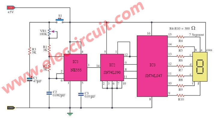
That site contains nothing but schematics taken from other websites: what's the point? I assume you have the permission from the authors. Design your own circuits or at least make improvements, to them. In this case could you please rewrite the poorly worded explanation.
It would be better if the NE555 were replaced with a CMOS oscillator such as the 74HC00 and the old TTL ICs with more modern HC equivalents. Of course the more economical solution would probably be to use a microcontroller: the no-thrills PIC16F54 would be perfect for this application.
Thank for comment. I think ic NE555 is small and low cost, it easy to use. -
Why post another circuit which basically does the same thing?
You don't even need a 555, it's possible to do this with a single CD4013 with one half configured as an astable. I prefer to use the modern 74HC74 though as it can drive LEDs brightly and run off a couple of AA cells.
Your idea are very good. Ic 74HC74 is small, but sure. Thank you. -
This is a review of electronic sound or a violent coin toss. With electronic circuits. This circuit uses integrated digital IC NE555 and CD4017 with LED display easily.
Principle of the circuit, when voltage is 5 volts to the circuit C1 will charge through the VR1 and R1 fully. IC1, R2, R3 and C2 to the astable multivibrator circuit.Rectangular waveform generator (Square Wave) sent out to pin 3 of IC1, through the trigger. (Which uses the T-on of the wave is a signal of the trigger), the pin 14 of IC2. This is the pin input, causing the output to come out to pins 3, the LED1 light LED2 goes out. When the signal came. The trigger pin 14 more to have come out to the output pin 2, the light LED1 LED2 off. The switch will stick together and when a trigger signal to the pin 14 again, to start new But because the astable multivibrator circuit acts rectangular waveform generator (Square Wave) with high frequency, it seems that the LED1 and LED2 is illuminated at all times. When the switch S1 open circuit (Open Circuit) to C1 discharged out through R1, VR1, VR2, R2, R3 and C1 and C2 discharge completely.
Make a circuit Stable multi-stop sensitivity Brett Foster rectangular signal generator (Square Wave), so we know that the LED lamps which display
-
This is a circuit diagram showing the random nature of LED 7 segment. In the diagram circuit IC1


Countdown timer with alarm
in General
Posted
Thank you for your comment.
I do not know if it's obsolete.
I think this circuit is interesting.
but is a little idea to apply many circuits.