

hotwaterwizard
-
Posts
2,022 -
Joined
-
Last visited
Content Type
Profiles
Forums
Events
Posts posted by hotwaterwizard
-
-
Here are a few 6v6 schematics. maybe one of them can help you figure it out.
Tube amps 6v6

[img width=680 height=594]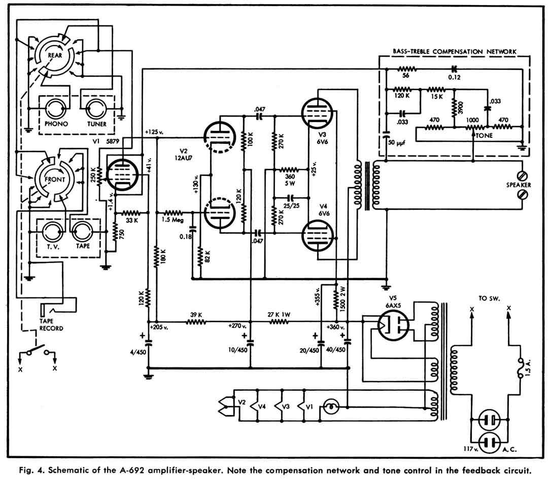
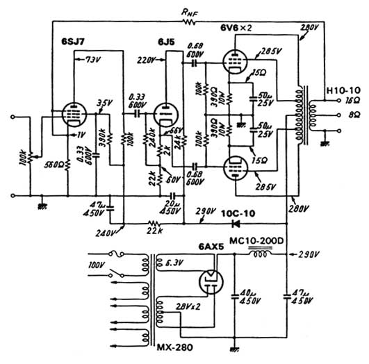
[img width=680 height=416]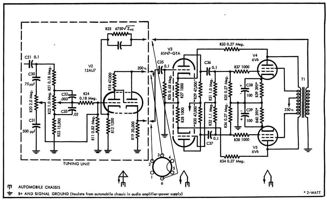


[img width=680 height=567]
-
Here is a Double Norm Open and Norm Closed
http://www.farnsworthelectronics.com/switches.htm
-
That is a large request. Here is something.
-
I will send it to you if you email me. STi5510 and STi5518
[email protected] -
I found the same Info on Electroda
MPF970 P-Channel JFET Motorola
2N3993
2N5114 -
Send detailed Pictures of the board and we may be able to make a schematic from it.
You know Reverse Engineer it. -
I also moderate Circuit Request board.
-
And here are a couple from our project section.
http://www.electronics-lab.com/projects/motor_light/024/index.html
http://www.electronics-lab.com/projects/sensors/001/index.htm -
Here are more


-
We could get similar Circuits for you but that one is proprietary.


-
I fixed it for you Steven.
You don't need to ask MP in my Forum. -
Here is another copy in PDF
Nice Job by the way.
Looks Great! ;) -
-
This is the best I could do.
-
Here is the real stuff.
http://www.allaboutcircuits.com/vol_1/chpt_1/7.html
http://www.mi.mun.ca/~cchaulk/eltk1100/ivse/ivse.htm
http://www.qrg.northwestern.edu/projects/vss/docs/Power/2-whats-electron-flow.html -
Is this the picture you are looking at?

They have written books about the way Electricity travels.
Lightning for example goes from the ground to the cloud.
Everyone thinks it is the other way around. But, if you film it with a slow motion camera you will see that it goes up not down.
http://www.sunblock99.org.uk/sb99/people/DMackay/lightning.html
Here is more on how electrons flow.
http://www.allaboutcircuits.com/vol_1/chpt_1/7.html
http://www.mi.mun.ca/~cchaulk/eltk1100/ivse/ivse.htm
http://www.qrg.northwestern.edu/projects/vss/docs/Power/2-whats-electron-flow.html -
http://www.kpsec.freeuk.com/components/74series.htm#74393
7490 decade (0-9) ripple counter
7493 4-bit (0-15) ripple counter
NC = No Connection (a pin that is not used).
# on the 7490 pins 6 and 7 connect to an
internal AND gate for resetting to 9.
For normal use connect QA to clockB and
connect the external clock signal to clockA.
These are ripple counters so beware that glitches may occur in any logic gate systems connected to their outputs due to the slight delay before the later counter outputs respond to a clock pulse.
The count advances as the clock input becomes low (on the falling-edge), this is indicated by the bar over the clock label. This is the usual clock behaviour of ripple counters and it means a counter output can directly drive the clock input of the next counter in a chain.
The counter is in two sections: clockA-QA and clockB-QB-QC-QD. For normal use connect QA to clockB to link the two sections, and connect the external clock signal to clockA.
For normal operation at least one reset0 input should be low, making both high resets the counter to zero (0000, QA-QD low). Note that the 7490 has a pair of reset9 inputs on pins 6 and 7, these reset the counter to nine (1001) so at least one of them must be low for counting to occur.
Counting to less than the maximum (9 or 15) can be achieved by connecting the appropriate output(s) to the two reset0 inputs. If only one reset input is required the two inputs can be connected together. For example: to count 0 to 8 connect QA (1) and QD (8) to the reset inputs.
Connecting ripple counters in a chain: please see 74393 below.
--------------------------------------------------------------------------------
http://www.kpsec.freeuk.com/components/cmos.htm
4029 up/down synchronous counter with preset
The 4029 is a synchronous counter so its outputs change precisely together on each clock pulse. This is helpful if you need to connect the outputs to logic gates because it avoids the glitches which occur with ripple counters.
The count occurs as the clock input becomes high (on the rising-edge). The up/down input determines the direction of counting: high for up, low for down. The state of up/down should be changed when the clock is high.
For normal operation (counting) preset, and carry in should be low.
The binary/decade input selects the type of counter: 4-bit binary (0-15) when high; decade (0-9) when low.
The counter may be preset by placing the desired binary number on the inputs A-D and briefly making the preset input high. There is no reset input, but preset can be used to reset the count to zero if inputs A-D are all low.
Connecting synchronous counters in a chain: please see 4510/16 below.
--------------------------------------------------------------------------------
4510 up/down decade (0-9) counter with preset
4516 up/down 4-bit (0-15) counter with preset
These are synchronous counters so their outputs change precisely together on each clock pulse. This is helpful if you need to connect their outputs to logic gates because it avoids the glitches which occur with ripple counters.
The count occurs as the clock input becomes high (on the rising-edge). The up/down input determines the direction of counting: high for up, low for down. The state of up/down should be changed when the clock is high.
For normal operation (counting) preset, reset and carry in should be low. When reset is high it resets the count to zero (0000, QA-QD low). The clock input should be low when resetting.
The counter may be preset by placing the desired binary number on the inputs A-D and briefly making the preset input high, the clock input should be low when this happens.
Connecting synchronous counters in a chain
The diagram below shows how to link synchronous counters, notice how all the clock (CK) inputs are linked. Carry out (CO) feeds carry in (CI) of the next counter. Carry in (CI) of the first counter should be low for 4029, 4510 and 4516 counters.
-
Here are just a few I found with a Keyword search "IC Logos"
http://www.elnec.com/iclogos_l.php
http://www.dibsplace.com/design/ICLogos.htm
http://www.chipdocs.com/logos/logotypes.html
http://www.dialelec.com/semiconductorlogos.html -
http://www.roboteq.com/robovia/electrical-diagram.pdf
http://www.cnhdd.com.cn/hdd/library/spvcm/eHA13561F.pdf -
Tuff one ???
ADP3011 Analog Devices
ADP3011
ADP3011JR-REEL Prog. synchronous switching reg. cntrl.
AR7120
IC Array -
Spanish Translation of PDF Above.
-
One more not Datasheet.
-
-
I have NAD3240PE


Schematics & Service Manuals
in Service Manuals
Posted
Here is a Request board you can upload and download Free!
http://www.denom.net/