

lmester
-
Posts
6 -
Joined
-
Last visited
Content Type
Profiles
Forums
Events
Posts posted by lmester
-
-
The meters came from A Chinese seller on EBay. I don't have a record of the seller. These meters are commonly available on EBay , Amazon, AliExpress etc.
-
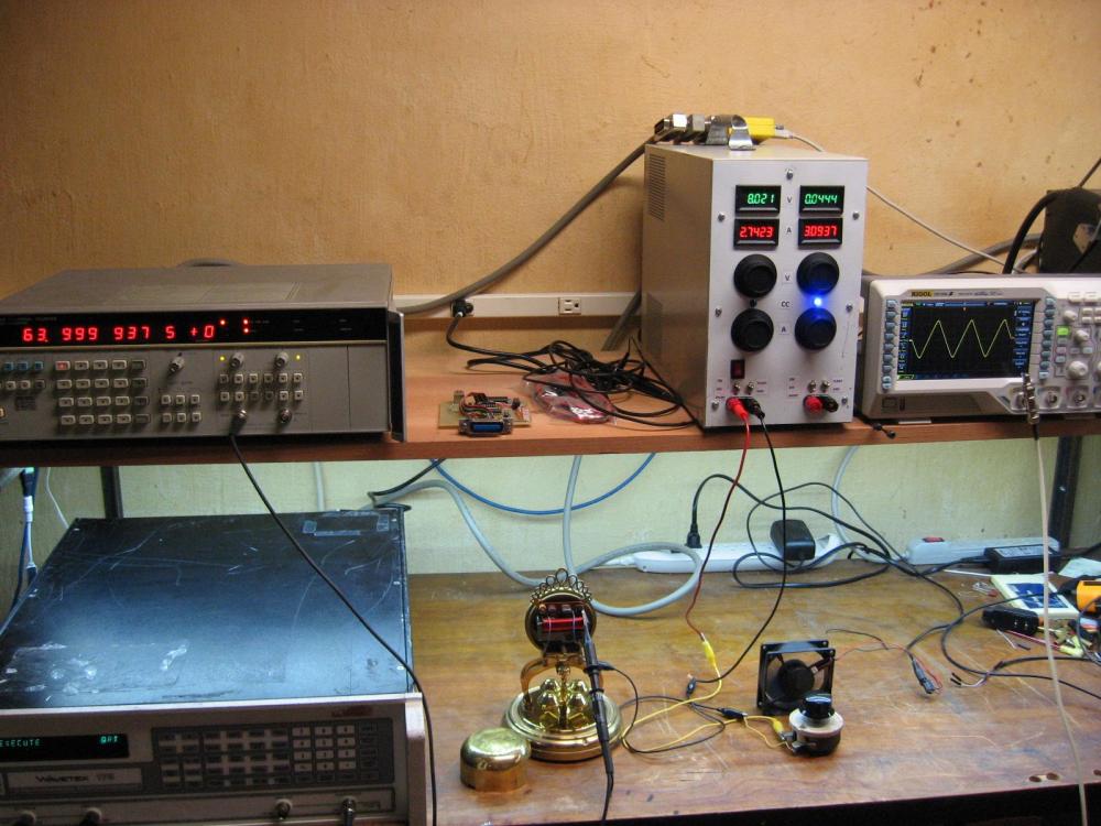
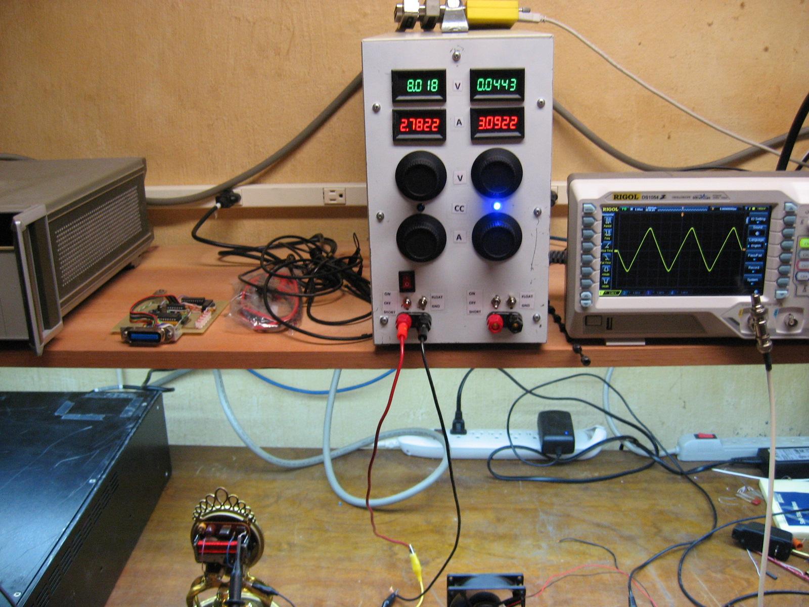
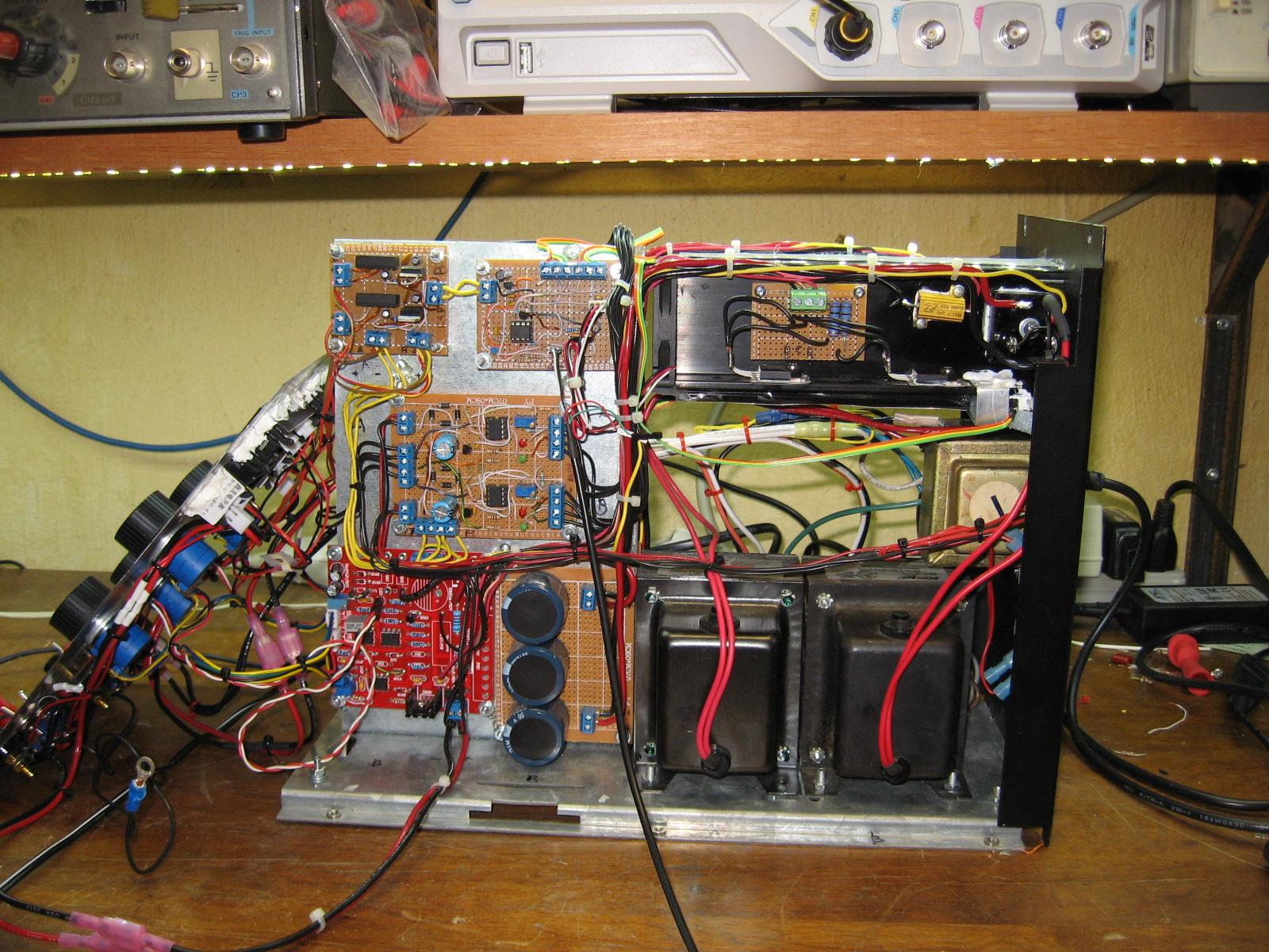
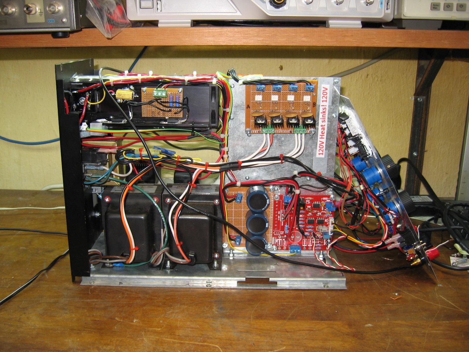
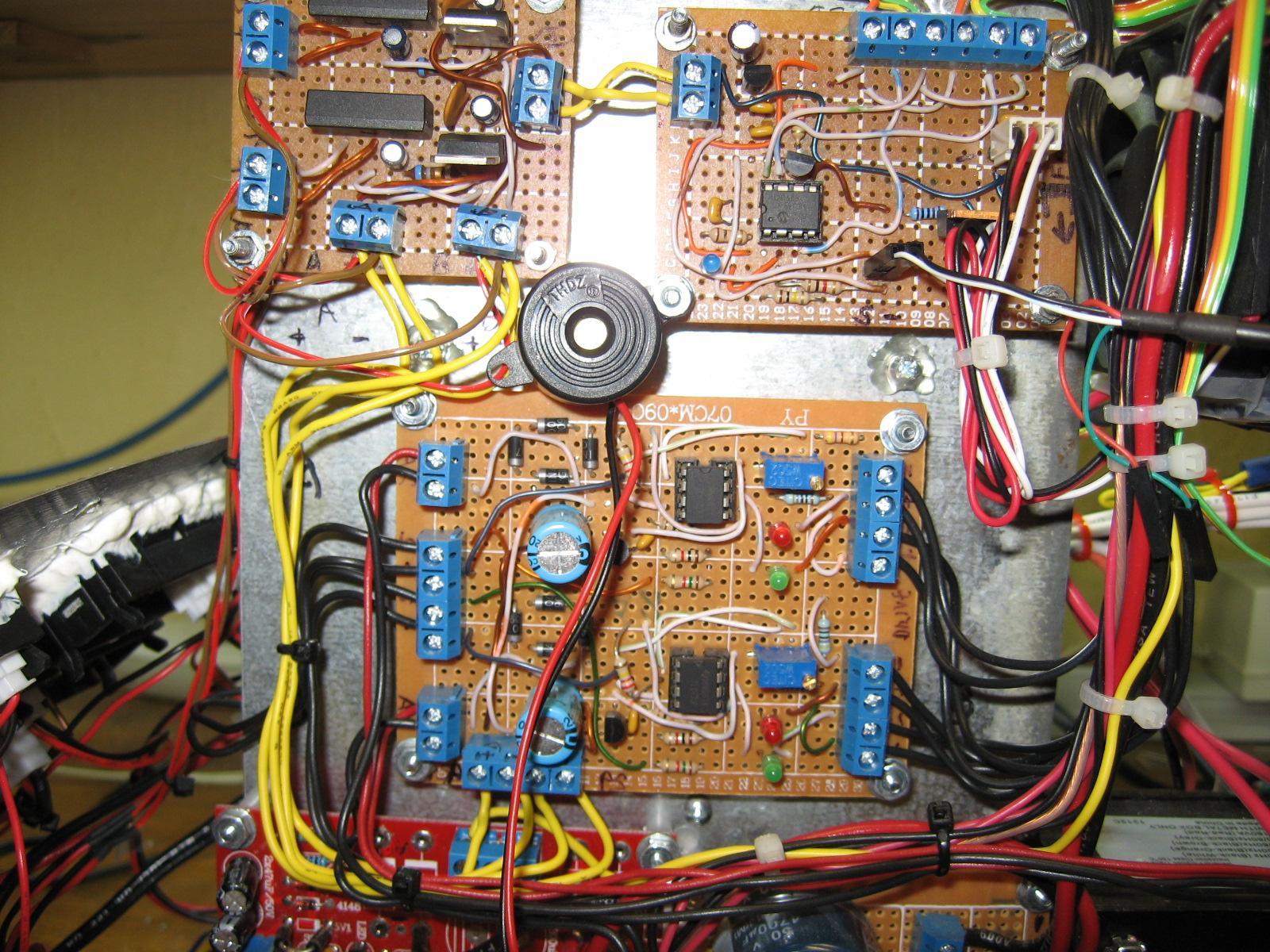
I finally have my power supply finished! It's on the shelf! I'm doing some full power tests.
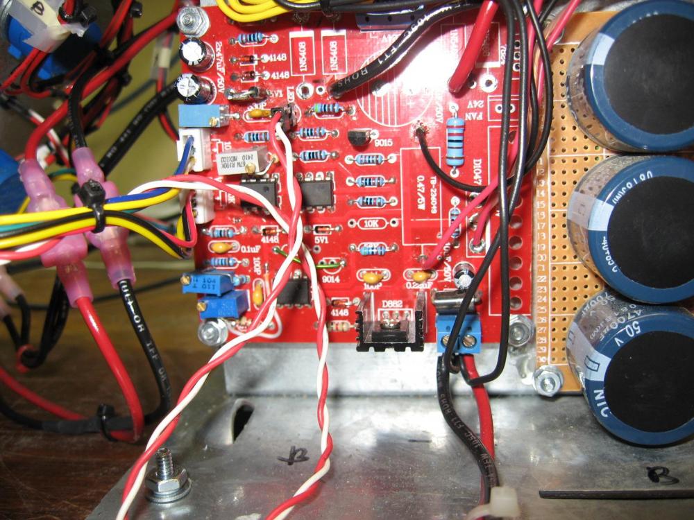
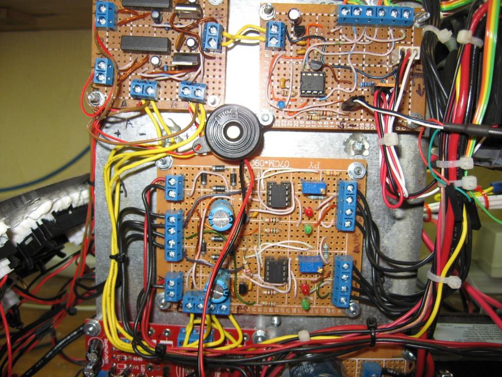
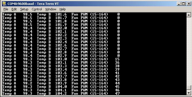
I Started with a pair of the Chinese circuit board kits. Lucky that I found this thread. I made the mods to the boards and added higher power components and PWM fan control.
My transformers have multiple primary voltage taps. I Used a comparator to select a higher transformer input voltage tap when the power supply output voltage is low. This greatly lowered the power Dissipation. With commercial power supplies this transformer voltage selection is done on the secondary of the transformer. With the transformers that I got for free, I could only switch primary winding taps. This required triac switching circuits.
Pictures are attached.


-
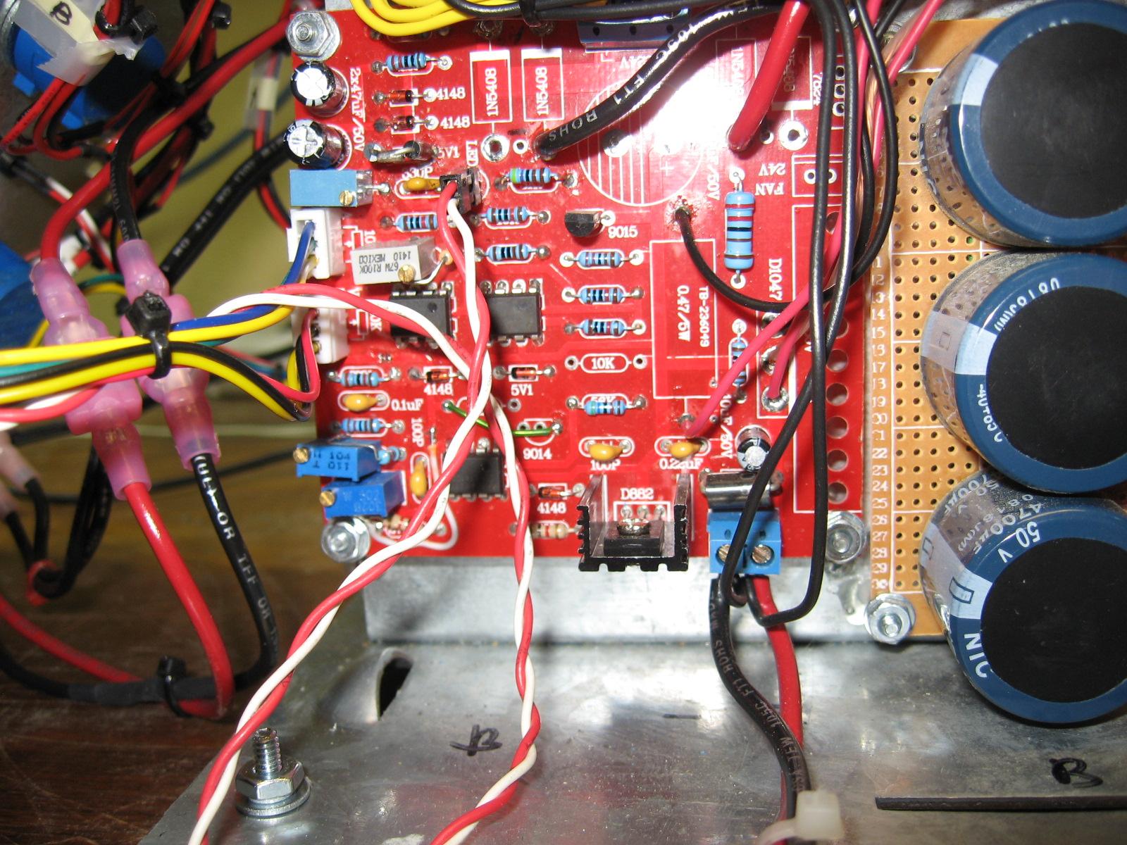
You know what? The current regulator opamp is the only one using the -1.3V supply that is half-wave rectified so if C3 is defective or is upside down then it produces 60Hz interference. 'scope the -1.3V supply to see.
Great job! I'd checked the positive supply and it's ripple was low. I forgot to check the negative supply. The negative supply has a lot of ripple. Now to troubleshoot that problem & get it fixed.
Thanks a bunch!
-
It is 60Hz from your electricity supply, not oscillation. Maybe you built the defective original circuit that has errors and many overloaded parts? The fixed and improved version is at the beginning of this thread. Maybe the tiny overloaded rectifier diodes failed or the transformer has burnt. The main filter capacitor has a value much too low. The original project cannot produce regulated 30V at 3A but maybe 25V at 3A instead or 30V at 1.5A. The original opamps are operating at a total supply voltage higher than their maximum allowed voltage and are noisy.
I should have provided more information. I built the revised circuit that uses the TLE2141 op amps.
Also, the noise only occurs when in constant current mode. It happens regardless of the voltage or current settings. I put a 100 ohm load on it with the voltage set to 10V. (100mA load). As I adjust the current set pot the noise increases as soon as it goes into constant current mode. Very similar to the scope traces I posted before. These were with the supply running at almost full load current. Also, I had 24VAC transformers available. With this transformer it will only maintain voltage regulation at full load up to a little more than 24VDC. I don't think this will cause any problem. I just set that maximum voltage adjust pot for 24V. So, I really only have a 0-24V supply. And finally the currennt regulation is working. It will maintain constant current. It's just noisy.
It'd be interesting to know if anyone else has scoped the output of their supply. Is there any difference in noise from CC to CV mode. If not then I need to find out what's causing the problem with mine.
-
I've built a power supply using this circuit. I noticed that it is noisy/oscillating when in constant current mode. When probing the circuit I see this oscillation on the current sense op-amp. Has anyone else seen this? Not a big problem for me as I'll probably only use CC to keep from letting the smoke out while testing a project
") It'd still be nice if I could fix this problem. I've mostly worked with digital electronics & embedded programming. My analog circuit skills are not the best. Any help would be appreciated.
It'd still be nice if I could fix this problem. I've mostly worked with digital electronics & embedded programming. My analog circuit skills are not the best. Any help would be appreciated.Attached are two scope captures of the supply output. One in CC and the other in CV mode.

0-30V Stabilized Power Supply
in Projects Q/A
Posted